- Specifications:
- DOCKQ
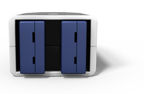
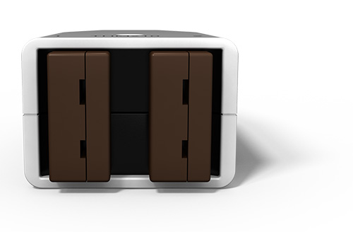
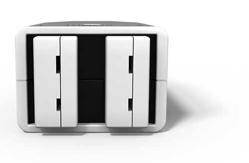
- MICROQ External Battery
- SubModules
- RackMounts and more
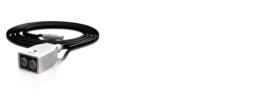
- Cables
ACCESSORIES: SPECIFICATIONS
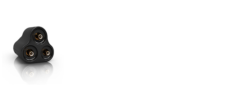
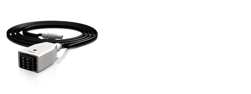
TBNC10
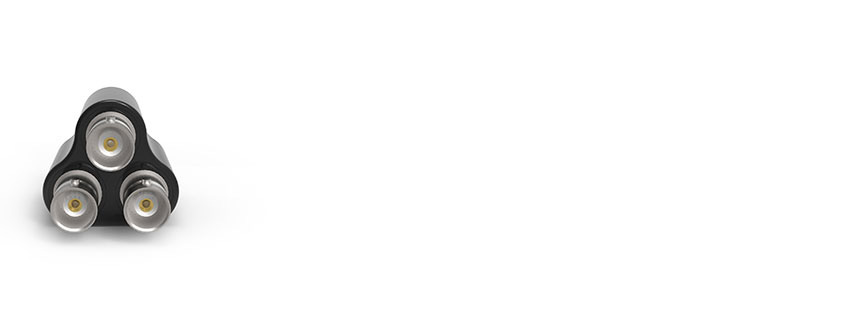
The TBNC10 is used to connect to the ICS42 Module. It splits signals from a 9-way LEMO® connector on the Module’s front panel to a single triangular prism with 3 BNC connectors to easily connect sensors. Three BNC connectors are provided on the SubModule to interface to the appropriate triaxial or single axis accelerometer. The SubModule connects to the ICS42 Module through a 300 mm, 500 mm or 1200 mm fly-lead.
Where used:
- With any ICP® based sensor commonly used to measure vibration, acceleration, force or pressure
- With any voltage source up to ±10 V in voltage input mode
- TBNC10 SubModules can be placed in a SubModule Rack for optimized cable management in 19 inch racks
TBNC10 options:
TBNC10 300
|
TBNC10 500
|
TBNC10 1200
|
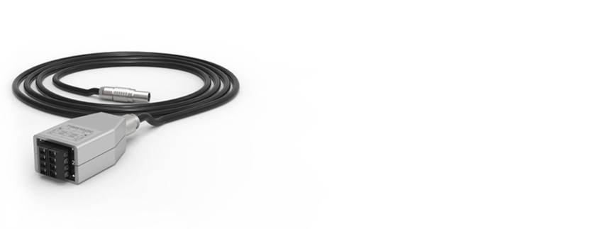
TBNC30
The TBNC30 is used to connect to the ICS42 Module. The Tri-BNC30 SubModule splits signals from a 9-way LEMO® FGG.0B, connecting on the Module’s front panel, to 3 single BNC Jack connectors to easily connect sensors. Three BNC Jack connectors are crimped on cables to provide a flexible interface to the appropriate triaxial or single axis accelerometer. The SubModule connects to the ICS42 Module through a 500 mm or 1200 mm fly-lead.
Where used:
- With any ICP® based sensor commonly used to measure vibration, acceleration, force or pressure
- With any voltage source up to ±10 V in voltage input mode
TBNC30 options:
TBNC30 500
|
TBNC30 1200
|
TBNC40
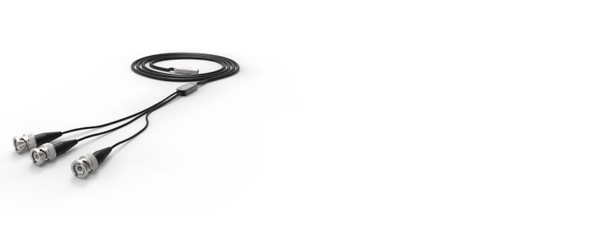
The TBNC40 is used to connect to the ICS42 Module. The Tri-BNC40 SubModule splits signals from a 9-way LEMO® FGG.0B, connecting on the Module’s front panel, to 3 single BNC Plug connectors to easily connect sensors. Three single BNC Plug connectors are crimped on cables to provide a flexible interface to the appropriate triaxial or single axis accelerometer.
Where used:
- With any ICP® based sensor commonly used to measure vibration, acceleration, force or pressure
- With any voltage source up to ±10 V in voltage input mode
TBNC40 options:
TBNC40 500
|
TBNC40 1200
|
TSMB10
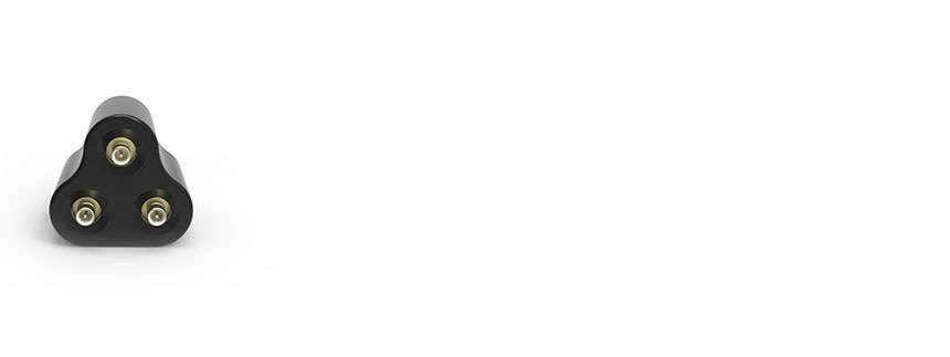
The TSMB10 is used to connect to the ICS42 Module. The Tri-SMB10 SubModule splits signals, from a 9-way LEMO® connector on the Module’s front panel, to 3 SMB connectors to easily connect sensors. Three SMB connectors are provided on the SubModule to interface to the appropriate triaxial or single axis accelerometer. The SubModule connects to the ICS42 Module through a 500 mm or 1200 mm fly-lead.
Where used:
- With any ICP® based sensor commonly used to measure vibration, acceleration, force or pressure
- With any voltage source up to ±10 V in voltage input mode
TSMB10 options:
TSMB10 500
|
TSMB10 1200
|
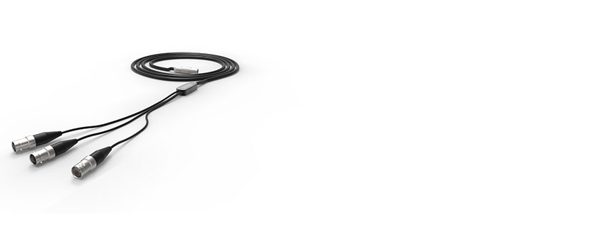
TMDT10
The TMDT10 is used to connect to the CHS42X Module Charge channels. The Tri-MDT10 SubModule splits signals from a 9-way LEMO® connector on the Module’s front panel to 3 UNF 10-32 MicroDot connectors to easily connect piezoelectric sensors. Three UNF 10-32 MicroDot connectors are provided on the SubModule to interface to the appropriate triaxial or single axis piezoelectric sensors/accelerometers. The SubModule connects to the CHS42X Module through a 500 mm or 1200 mm fly-lead.
Where used:
- With any piezoelectric sensor commonly used to measure vibration, acceleration, force or pressure
ICTV11
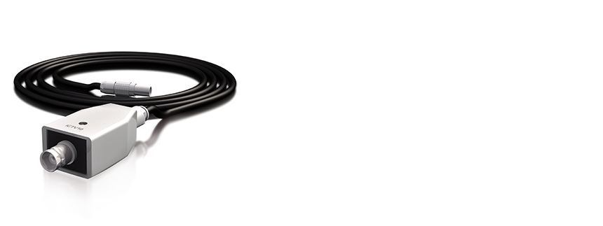
The ICTV11 is used to protect the ICT42 or ICT42S Module’s Tacho inputs from excessively high voltages. This may occur when inductive devices are discharged or when measurements are conducted close to high voltage circuitry. The SubModule contains high energy over-voltage dissipation devices.
These devices limit the output voltage to reasonable values which will not destroy the internal circuitry of the Modules. The SubModule connects to ICT42 or ICT42S Modules through a 300 mm fly-lead ending with a 4-way LEMO® FGG.0B connector.
Where used:
- One ICTV11 can support one channel on an ICT42 or ICT42S Module
- Designed as a SubModule used to protect a Tacho channel from excessively high voltages
- Accepts one 4-way LEMO® FGG.0B connector
- Provides a BNC connector to interface with the appropriate Tacho sensor
FLXB20

The FLXB20 SubModule provides an interface to a 9-way D-sub connector. The FLXB20 SubModule is used to connect an FLX42 Module to a FlexRay™ network.
It provides the interface between the 7-way LEMO® connector on an FLX42 Module and the 9-way D-sub connector on a FlexRay™ network.
Where used:
- Designed as a SubModule used to connect 1 channel of an FLX42 Module to a FlexRay™ network
- Accepts a single 7-way LEMO® FGG.0B connector
- The FLXB20 provides the interface to the 9-way D-sub connector on a FlexRay™ network over a 300 mm or 3000 mm cable
FLXB20 options:
FLXB20 300
|
FLXB20 3000
|
CANC10
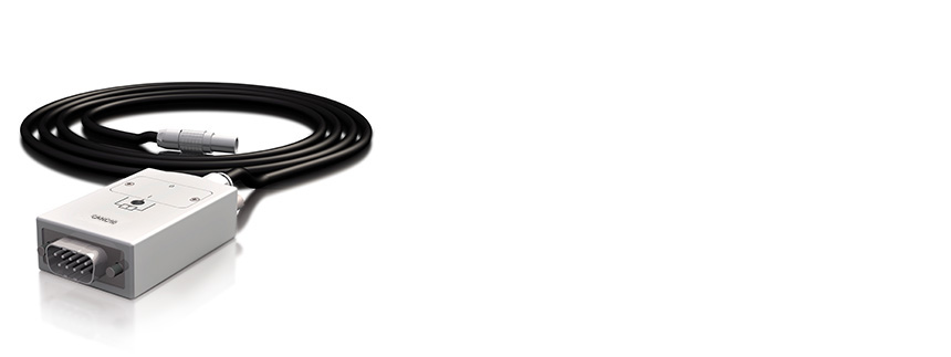
The CANC10 SubModule provides an interface to a 9-pin D-sub connection. The CANC10 SubModule is used to connect the built-in CAN / CAN FD channel on the MICROQ to a CANbus network. It can also connect the CAN42S Module to a CANbus network. It provides the interface between the 7-pin LEMO® connector on the built-in CAN connector and the 9-pin D-sub connector on the CANbus network.
Where used:
- Connects a built-in CAN / CAN FD channel on the MICROQ to a CANbus network (300 mm or 3000 mm cable length)
- Accepts a single 7-pin LEMO® FGG 0B connector
- Provides the interface to the 9-pin D-sub connector on the CANbus network over a 300 mm or 3000 mm cable (recommended length is 300 mm)
CANC10 options:
CANC10 300
|
CANC10 3000
|
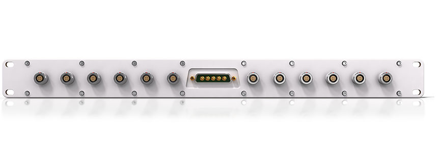
The PSDP10 is a multiport power distribution panel for powering multiple DECAQ chassis. The panel (which is designed to be mounted in a 19 inch rack) is supplied power through a 5-way high power D-subminiature port and provides power to 12 recipient DECAQ chassis through 4-way LEMO® connectors.
Where used:
- One PSDP10 supplies power for up to 12 DECAQ chassis
- Designed according to a 1.5 U form factor for mounting in 19 inch racks
- Accepts power through a 5-pin high power D-subminiature port
- The PSDP10 provides twelve 4-way LEMO® connectors
Cable options for the PSDP10:
| 223K | The 023K is a standard length (3 m) power cable used to power DECAQ chassis. 4-pin LEMO® to 4-pin LEMO® |
| 300K | The 300K is a standard length (1.2 m) power cable used to supply power from an external power supply to the PSDP10. 5-power-pin D-sub connector to ring terminals |
Seven thermocouple based SubModules are available, each containing dedicated thermocouple connectors. Each SubModule contains a pair of miniature thermocouple connectors, of the appropriate alloy and color, according to either IEC or ANSI standards. Cold-junction-compensation is facilitated through the use of a 0.5 °C accurate temperature sensor in thermal contact with the connectors’ contacts.
The SubModule type is identified through a TEDS interface. Each SubModule connects to a THM42 Module through a 300 mm fly-lead ending with a 7-pin LEMO® FGG.0B connector.
THE FOLLOWING THERMOCOUPLE SUBMODULES ARE AVAILABLE:
THMP10
The THMP10 SubModule is used in conjunction with a THM42 Module to provide two sets of 4-way LEMO® EGG.0B connectors to use with two Pt100 sensors. These connectors provide current to a Pt100 sensor and sense the voltage across it. The SubModule type is identified through a TEDS interface.
The THMP10 SubModule connects to a THM42 Module through a 300 mm fly-lead ending with a 7-pin LEMO® FGG.0B connector.
Where used:
- One THMP10 can support two channels on a THM42 Module by linking the channels to two sensors
- Designed as a SubModule used to expand the capacity of a THM42 Module
- Accepts 1 7-way LEMO® EHG.0B connector
- Provides two sets of 4-way LEMO® EGG.0B connectors for use with Pt100 sensors
THMS10
The THMS10 SubModule is used in conjunction with a THM42 Module to provide two sets of 4-way general purpose screw terminals to connect to a pair of E, J, K or T thermocouples or a pair of Pt100 sensors. Cold-junction-compensation is facilitated through the use of a 0.5 °C accurate temperature sensor in thermal contact with the connectors’ contacts. Constant current is provided for Pt100 use. The SubModule type is identified through a TEDS interface.
The THMS10 SubModule connects to a THM42 Module through a 300 mm fly-lead ending with a 7-pin LEMO® FGG.0B connector.
Where used:
- One THMS10 can support two channels on a THM42 Module by linking the channels to two sensors
- Designed as a SubModule used to expand the capacity of a THM42 Module
- Accepts one 7-way LEMO® EHG.0B connector
- Provides two sets of 4-way general purpose screw terminals to connect to Pt100 or Thermocouple sensors
THMV10
The THMV10 SubModule is used in conjunction with a THM42 Module. It provides two sets of 4-way screw terminals to connect to 2 constant current signals between 4 mA and 20 mA. Two precision 250 Ω resistors convert the constant current signals to voltage signals between 1 V and 5 V. The SubModule is identified through a TEDS interface.
The THMV10 SubModule connects to a THM42 through a 300 mm fly-lead ending with a 7-pin LEMO® FGG.0B connector.
Where used:
- One THMV10 can support two channels on a THM42 Module
- Accepts one 7-way LEMO® EHG.0B connector
- Provides two sets of 4-pin screw terminals
- Converts constant current signals between 4 mA and 20 mA to voltages between 1 V and 5 V
QBNC12
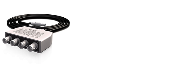
The Quad BNC (QBNC12) is a SubModule that is used to split signals from a 7-way LEMO® connector through a 500 mm fly-lead ending with 4 BNC connectors. A sticker on top indicates with which Modules the QBNC12 is compatible, and how the signals are mapped. The SubModule is compatible with ALO42S, WSB42, WSB42X and ALI42.
Where used:
- One QBNC12 is used to split the signals coming from an ALO42S Module
- Designed as a SubModule used to expand the capacity of an ALOP42S Module
- Accepts one 7-way LEMO® FGG.0B connector
- Can also be used with the WSB42, WSB42X and ALI42
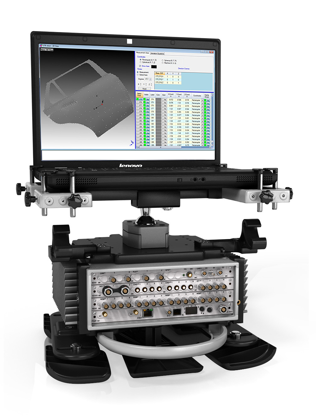
SeatFrame
The SF10 optimally secures a 2, 3, 4 or 6-slot chassis and notebook onto a car seat for mobile measurements. It consists of machined aluminum members which can be adjusted to optimally fit the seat, chassis and notebook. To prevent sideways movement, once placed on the seat, the side and rear feet can be adjusted to best hug the seat. The rear SeatFrame handle can also be adjusted to push against the seat’s backrest to prevent it flipping over. It is strapped to the seat using the safety belt.
A notebook is placed on an adjustable platform mounted above the DECAQ which can fit any notebook size. It is fastened into position by restraining posts which can easily be loosened to remove the notebook. Multiple settings and adjustments allow the notebook to be placed in the position that best suits the user. The SeatFrame is ergonomically designed, easy to carry and extremely robust.
SEATFRAME
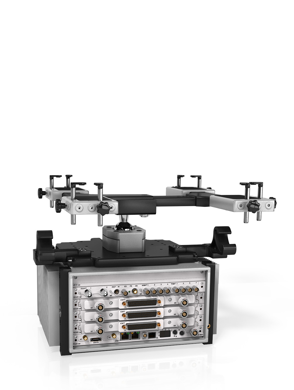
NOTEBOOK PLATFORM
CHASSIS SUPPORT
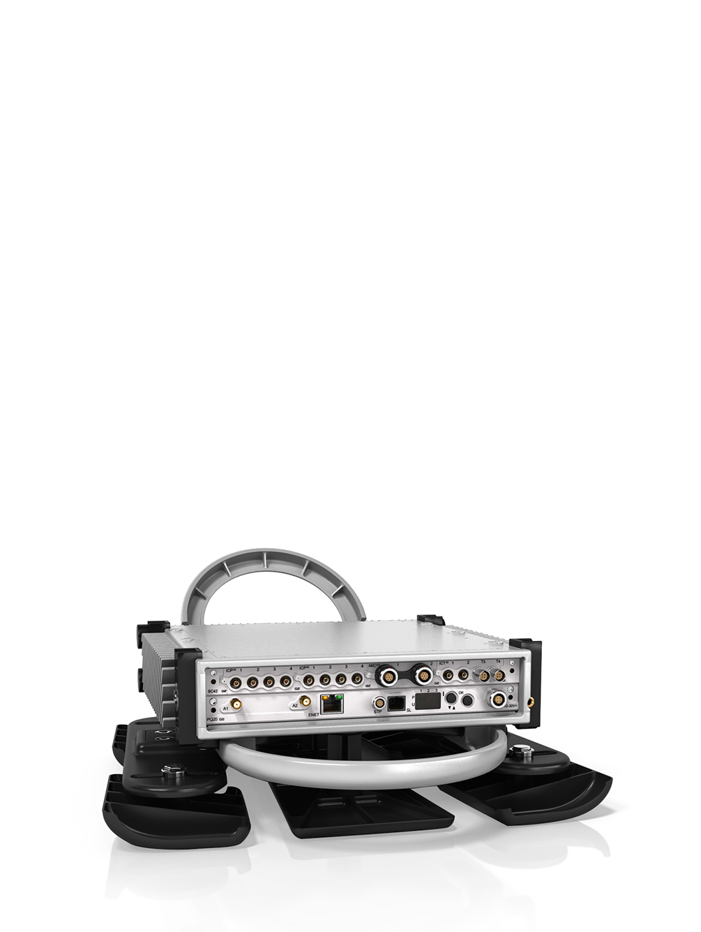
Mobile Mount
The Mobile Mount distributes all measuring channels from the chassis front end to BNC connectors on the left-hand side of the Mount. The BNC connectors are easily accessible and simplify cabling for portable measurements.

Where used:
- The Mobile Mount can support up to 170 voltage and ICP® channels as well as additional Tacho input channels
- When sensor cabling needs to be simplified by accepting only BNC connectors
- When neat sensor configuration is needed for a portable measurement
- With any ICP® based sensor commonly used to measure vibration, acceleration, force or pressure
- With any voltage source up to ±10 V in voltage input mode
The RackMount is a compact, machined from aluminium Rack Mounting Kits which house 2, 3, 4, 6 and 10-slot DECAQ chassis. The chassis has specifically been recessed in each Mounting Kit to ensure that all cables are contained behind the rack’s front face. These cables can then be routed to the left and right sides of the chassis. At the rear, a horizontal brace provides a mounting point for cable connector flanges should this be required. This is particularly useful in cases where a conversion of connector types is required between those used by the DECAQ and those used by the testing facility. The sides and rear of the Mounting Kit have been left open to allow air to enter from the bottom of the rack to properly cool each chassis.
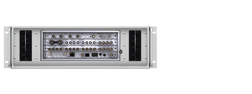
19” RACK MOUNT KIT FOR DECAQ 02/03/04
| 3U 19” rack mount, 477 mm (19”) depth, machined aluminum |
| DECAQ set back is adjustable and designed to ensure that all cables can be contained behind the rack’s front face |
| Easy cable management with brush pass-throughs on the left and right sides and mounting points in the rear |
RM04 houses an DECAQ 2, DECAQ 3 or DECAQ 4 chassis
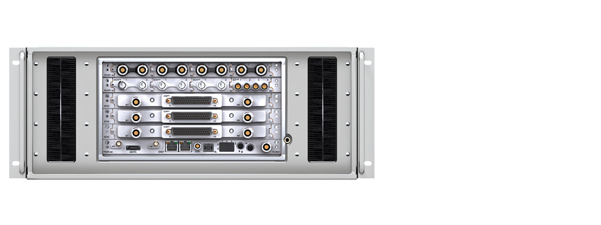
19” RACK MOUNT KIT FOR DECAQ 06
| 4U 19” rack mount, 557 mm (22”) depth, machined aluminum |
| DECAQ set back is adjustable and designed to ensure that all cables can be contained behind the rack’s front face |
| Easy cable management with brush pass-throughs on the left and right sides and mounting points in the rear |
RM06 houses an DECAQ 6 chassis
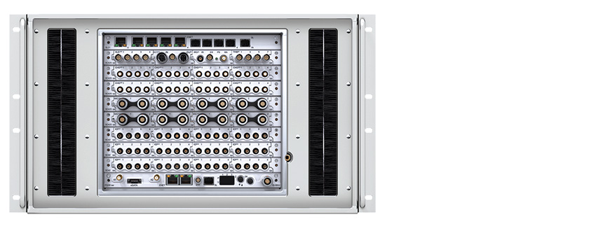
19” RACK MOUNT KIT FOR DECAQ 10
| 6U 19” rack mount, 557 mm (22”) depth, machined aluminum |
| DECAQ set back is adjustable and designed to ensure that all cables can be contained behind the rack’s front face |
| Easy cable management with brush pass-throughs on the left and right sides and mounting points in the rear |
RM10 houses an DECAQ 10 chassis
SubModule Rack (SMRM20)
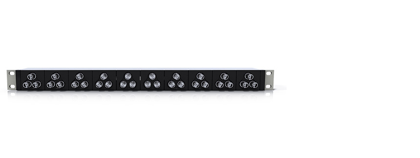
The SMRM20 is a panel designed to house various SubModules in a 19 inch rack.
Where used:
- One SMRM20 provides housing for any SubModule. The number of SubModules that can be housed will depend on the type and width of the SubModule being used
- Designed according to a 1 U form factor for mounting in 19 inch racks
- Accepts any SubModule type
- The SMRM20 provides a convenient and neat location for placing SubModules connected to a DECAQ Chassis mounted in a rack