Match Your Sensor
WITH OUR SIGNAL CONDITIONING AMPLIFIERS
| PARAMETER | NO. OF CHANNELS | MAXIMUM DATA RATE | RESOLUTION | MODULE |
|---|---|---|---|---|
| ICP® based microphones, accelerometers, load cells and pressure sensors | ||||
| 6 | 102.4 kSa/s | 24-bit | ICS42; CHS42X | |
| 2 | 204.8 kSa/s | 24-bit | ICT42S 2 ; MIC42X | |
| 4 | 204.8 kSa/s | 24-bit | ICP42S ; WSB42X | |
| ±10 V voltage input | 8 | 6.4 kSa/s | 24-bit | THM42 |
| 6 | 102.4 kSa/s | 24-bit | ICS42 ; CHS42X | |
| 2 | 204.8 kSa/s | 24-bit | ICT42S 2 ; MIC42X | |
| 4 | 204.8 kSa/s | 24-bit | ICP42S ; WSB42X | |
| 2 | 5 MSa/s | 24-bit | ALI25 ; | |
| ±60 V voltage input | ||||
| 4 | 204.8 kSa/s | 24-bit | ICP42S ; | |
| Tacho pulse input with 4.9 MSa/s Scope Mode | 2 | up to 700 Kpulse/s1 | 20 ns | ICT42S 1 |
| 200 V or non-polarized microphones | 2 | 204.8 kSa/s | 24-bit | MIC42X |
| Piezoelectric based accelerometers, load cells, etc. (Single-Ended) | 6 | 102.4 kSa/s | 24-bit | CHS42X |
| Piezoelectric based accelerometers, load cells, etc. (Differential) | 2 | 204.8 kSa/s | 24-bit | DCH42S |
| Strain gauges, load cells, pressure sensors, strain based accelerometers, inductive displacement (LVDT) and rope displacement sensors | 4 | 204.8 kSa/s | 24-bit | WSB42X |
| 2 | 5 MSa/s | 24-bit | ALI25 | |
| Current-excited strain gauges including dynamic strain | 4 | 204.8 kSa/s | 24-bit | WSB42X |
| E, J, K, T and U thermocouples as well as Pt100 sensors | 8 | 6.4 kSa/s | 24-bit | THM42 |
| Piezoresistive sensors (Shock/Hopkinson Bar Testing) | 2 | 5 MSa/s | 24-bit | ALI25 |
| PARAMETER | NO. OF CHANNELS | MAXIMUM DATA RATE | RESOLUTION | MODULE |
|---|---|---|---|---|
| ±10 V voltage output with status handshake | 4 | 204.8 kSa/s | 24-bit | ALO42S |
- Specification Comparison:
- Analog
- Output
- Digital
- Specifications:
- Analog
- ICS ICP® / Voltage
- ICP Advanced ICP® / Voltage
- CHS ICP® / Voltage
- DCH Differential Charge
- ICT Advanced ICP® / Voltage and Tacho
- THM Thermocouple and Pt100
- WSB Bridge, ICP® and Voltage
- ALI High-Speed Bridge and Voltage
- MIC Microphone, ICP® / Voltage
- Output
- ALO Voltage Output
- Digital
- CAN CAN Network Interface
- GPS GPS Interface
MODULES: SPECIFICATIONS
ICS42
6 Channel ICP® and Voltage Input Amplifier
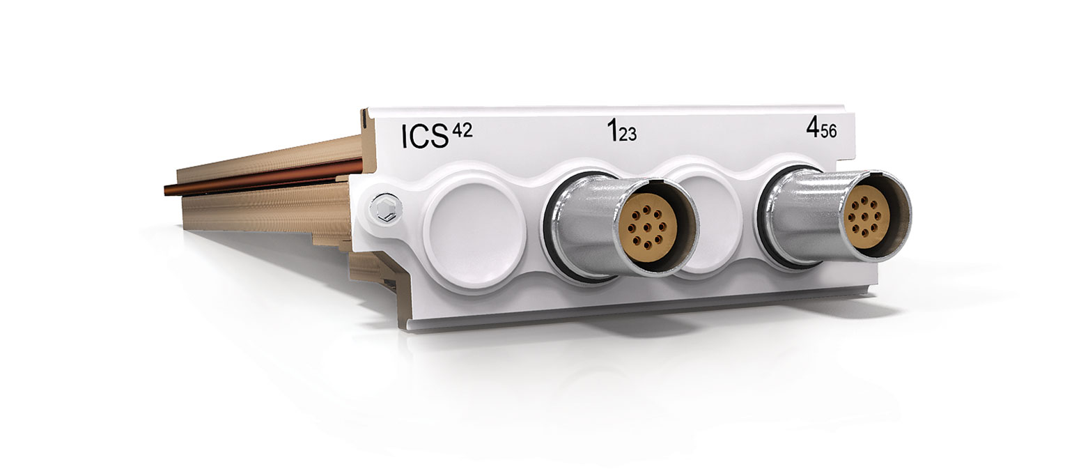
The ICS42 Module can be used with ICP® based accelerometers, force and pressure sensors as well as to measure analog voltages. All 6 channels can operate independently of each other, each with their own setting of mode, gain and coupling.
Where used:
- With any ICP® based sensor commonly used to measure vibration, acceleration, force or pressure
- With any voltage source up to ±10 V in voltage input mode
ICS42 features:
- 6 channels
- 2 input modes of operation:
- ICP® mode with 4 mA constant current at 24 V excitation
- Voltage input mode with AC or DC coupling
- Supports TEDS IEEE 1451.4 V0.9, V1.0 (Class 1)
- 24-bit resolution, 102.4 kSa/s sampling rate per channel,
- 44.3 kHz bandwidth
- < 0.2° @ 10 kHz phase accuracy when in similar range
- ±(100 mV, 1 V and 10 V) input ranges
- Highly configurable to accommodate single ended and triaxial sensors
- Supports a number of known industries triaxial cables
- Short and open circuit cable monitoring
- Selectable low and high pass digital filters
- 2 MΩ Differential and 1 MΩ Single-Ended input impedance
- LEMO® 9-pin EHG.0B connectors
- Low power consumption
ICP42S
Advanced 4 Channel ICP® and Voltage Input Amplifier
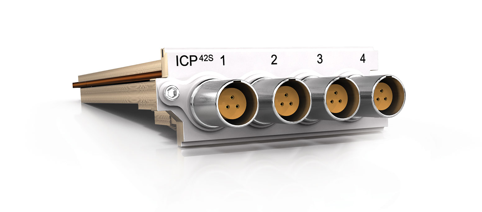
The ICP42S Module can be used with ICP® based accelerometers, force and pressure sensors as well as to measure analog voltages. All 4 channels operate independently of each other, each with their own setting of mode, gain and coupling.
Where used:
- With any ICP® based sensor commonly used to measure vibration, acceleration, force or pressure
- With any voltage source up to ±60 V in voltage input mode
ICP42S features:
- 4 channels
- 2 input modes of operation:
- ICP® mode with 4 mA, 8 mA or 12 mA constant current at 24 V excitation
- Voltage input mode with AC or DC coupling
- Supports TEDS IEEE 1451.4 V0.9, V1.0 (Class 1)
- 24-bit resolution, 204.8 kSa/s sampling rate per channel, 100 kHz bandwidth
- < 0.2° @ 10 kHz phase accuracy between channels of the same or any other Module
- ±(100 mV, 1 V, 10 V and 60 V) input ranges
- There are 3 distinctive input mode
options for both ICP® and voltage input modes:
- Differential or Balanced Float
- Single-Ended or Unbalanced Float
- Single-Ended or Unbalanced Ground
- Short and open circuit cable monitoring
- Signal integrity circuit continuously monitors the input and disconnects sensitive circuits during overload conditions
- Pre- and post-filter overflow monitoring
- Selectable low and high pass digital filters
- 2 MΩ Differential and 1 MΩ Single-Ended input impedance
- LEMO® 3-pin EHG.0B connectors
- Low power consumption
Related Cables:
- 308K – Signal cable, converting LEMO® (3-pin) connector to BNC Jack connector
CHS42X
6 Channel Charge, ICP® and Voltage Input Amplifier
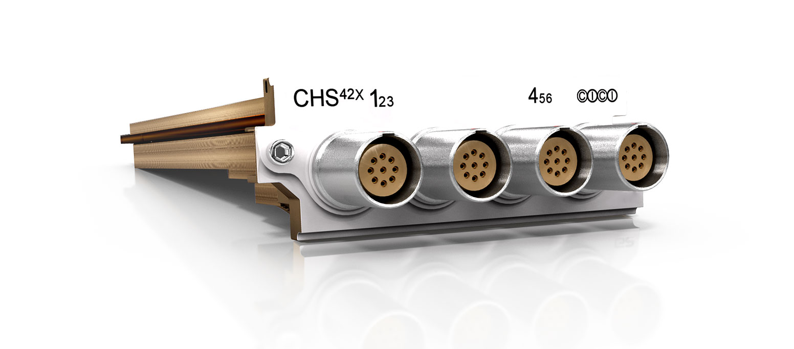
The CHS42X Module can be used with ICP® based accelerometers, force and pressure sensors, quartz or piezoelectric ceramic sensors or to measure analog voltages.
Where used:
- With any ICP® based sensor commonly used to measure vibration, acceleration, force or pressure
- With piezoelectric sensors commonly used to measure vibration, acceleration, force, torque and pressure
- With any voltage source up to ±10 V in voltage input mode
ICP® and Voltage Mode features
- 6 channels
- ICP® mode with 4 mA constant current at 24 V excitation
- Voltage input mode with AC or DC coupling
- Supports TEDS IEEE 1451.4 V0.9 V1.0 (Class 1)
- 24-bit resolution, 102.4 kSa/s sampling rate per channel, 44.3 kHz bandwidth
- Highly configurable to accommodate triaxial sensors
- Supports a number of known industries triaxial cables
- Short and open circuit cable monitoring
- Signal integrity circuit continuously monitors the input and disconnects sensitive circuits during overload conditions
- Pre- and post-filter overflow monitoring
- Selectable low and high pass digital filters
- Low power consumption
- LEMO® 9-pin EHG.0B connectors
Charge Input Mode features
- 6 channels
- 24-bit resolution, 102.4 kSa/s sampling rate per channel, 44.3 kHz bandwidth
- Drift is lower than 4 mV/h at any sensitivity and gain
- The cable shield can be connected or disconnected from the module ground
- Low power consumption
- High input impedance
- Selectable low and high pass digital filters
- LEMO® 9-pin EHG.0B connectors
DCH42S
2 Channel Differential Charge
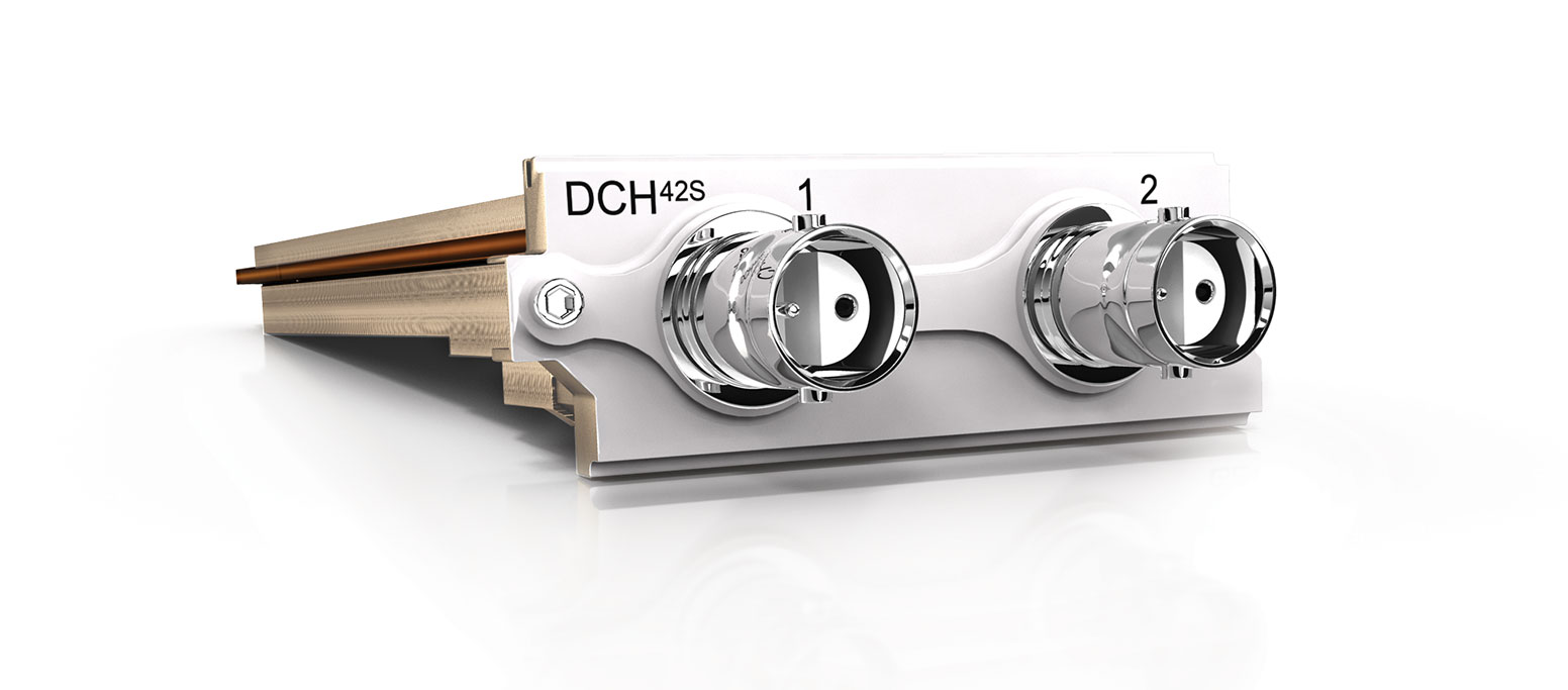
The DCH42S Module has 2 independent differential input channels for Quartz or Piezoelectric Ceramic sensors. These sensors are typically used when improved signal performance, such as low noise and low distortion, is required, or where high temperature and nuclear radiation prevents the use of ICP® based sensors. A differential charge measurement also offers further noise immunity and higher bandwidth which makes it particularly useful for applications using long cables.
Where used:
- With piezoelectric sensors commonly used to measure vibration, acceleration, force, torque and pressure
- Where long cables are required necessitating the use of balanced twisted pair cables
DCH42S features:
- 2 channels
- There are 2 modes of operation:
- Single-Ended
- Differential
- 24-bit resolution, 204.8 kSa/s sampling rate per channel, 90 kHz bandwidth
- < 0.5° @ 10 kHz phase accuracy when in similar range
- 2 Sensitivity settings of 0.1 mV/pC and 1 mV/pC when in Single-Ended mode
- 2 Sensitivity settings of 0.2 mV/pC and 2 mV/pC when in Differential mode
- ±(100 mV, 1 V and 10 V) input ranges
- Maximum charge input ranges from ±10 000 pC to ±100 000 pC in Single-Ended mode and from ±5000 pC to ±50 000 pC in Differential mode
- Low discharge time constant provides between 0.016 Hz and 1.6 Hz high pass frequency (-3 dB), depending on mode
- Selectable low and high pass digital filters
- Overvoltage detection on frontend input signals
- Amphenol 31-2225 Twin BNC connectors
- Low power consumption
ICT42S
Advanced 2 Channel ICP® Voltage Input Amplifier with 2 Channel Tacho Input Amplifier
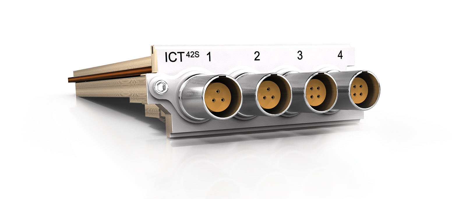
The ICT42S Module is a hybrid Module which combines 2 channels from the ICP42S Module with 2 Tacho input channels. The Tacho channels provide Tacho period measurements with a 20 ns resolution, sampled when the signal intersects its trigger level settings. Triggering of Tacho signals can be set for rising or falling edges with adjustable hysteresis while additionally providing AC coupling for sensors with varying DC voltage offsets. A high speed 4.9 MSa/s scope mode is provided to view the Tacho signals in order to assist with the definition of trigger levels.
Where used:
- When measuring the pulse rate and time between pulses such as rpm and crank angle
- With any ICP® based sensor commonly used to measure vibration, acceleration, force or pressure
- With any voltage source up to ±60 V in voltage input mode
ICT42S features: ICP® channels
- 2 ICP® channels
-
2 input modes of operation
- ICP® mode with 4 mA, 8 mA or 12 mA constant current at 24 V excitation
- Voltage input mode with AC or DC coupling
- Supports TEDS IEEE 1451.4 V0.9, V1.0 (Class 1)
- 24-bit resolution, 204.8 kSa/s sampling rate per channel, 100 kHz bandwidth
- < 0.2° @ 10 kHz phase accuracy between channels of the same or any other Module
- ±(100 mV, 1 V, 10 V and 60 V) input ranges
-
There are 3 distinctive input mode options for both ICP® and voltage input modes:
- Differential or Balanced Float
- Single-Ended or Unbalanced Float
- Single-Ended or Unbalanced
- Short and open circuit cable monitoring
- Signal integrity circuit continuously monitors the input and disconnects sensitive circuits during overload conditions
- Pre- and post-filter overflow monitoring
- Selectable low and high pass digital filters
- 2 MΩ Differential and 1 MΩ Single-Ended input impedance
- LEMO® 3-pin EHG.0B connectors
- Low power consumption
ICT42S features: Tacho channels
- 2 Tacho channels
- Tacho input can be DC/AC coupled
- 20 ns (50 MHz) Tacho resolution
- 16-bit Tacho trigger level adjustment
- ±(2 V, 12 V, 30 V and 60 V) input ranges
- 2 MHz analog bandwidth for all input ranges
- Adjustable trigger level hysteresis (Schmitt trigger implementation)
- Triggering on the n’th edge
- Tacho trigger level self-calibration
- Scope mode for each Tacho channel, sampled at 4.9 MSa/s resolution
- ±12 V or 12 V voltage excitation output to Tacho sensor
- LEMO® 4-pin EHG.0B connectors
- Low power consumption
- 700 kPulse/s rate for the sum of the 2 Tacho channels
Related Cables:
Related SubModule:
- ICTV11 – Used to protect Tacho inputs from excessively high voltages. Provides a BNC connector to interface to the appropriate Tacho sensor
THM42
8 Channel E, J, K, T and U Thermocouple and Pt100 Input Amplifier
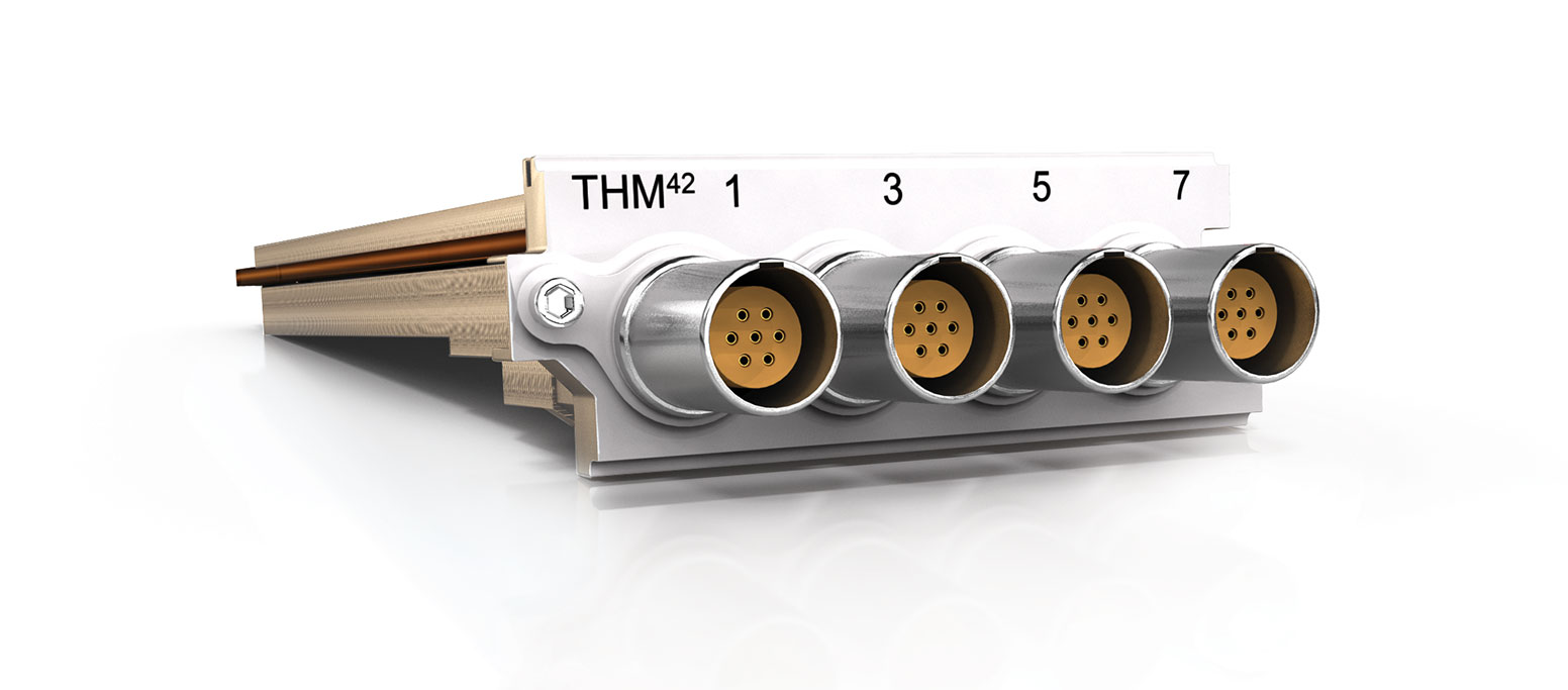
The THM42 Module contains 8 channels for use with any thermocouple-type as well as Pt100 sensors. Remote cold-junction compensation is provided through a SubModule (which is thermocouple-type specific) while linearization is provided in the Signal Conditioning Board. The Module also includes a calibrated 0.2 mA current source for Pt100 sensor excitation. SubModules are available which contain a pair of commonly used miniature E, J, K, T and U thermocouple connectors (other types available upon request) with cold-junction circuitry for thermocouple applications. Another SubModule contains a pair of LEMO® connectors for Pt100 applications. Any combination of applicable SubModules can be connected to the THM42 Module. The Module also includes 8 channels for measuring voltage inputs up to ±10 V.
Where used:
- When measuring E, J, K, T or U thermocouples (other types available upon request)
- When measuring Pt100 sensors in constant current mode
- With any voltage source up to ±10 V in voltage input mode
THM42 features:
- 8 channels
- 3 input modes of operation:
- Thermocouples
- Pt100 based temperature measurement
- Voltage input mode, including 4 mA to 20 mA sensors
- Supports TEDS IEEE 1451.4 V0.9, V1.0 (Class 2)
- 24-bit resolution, 6.4 kSa/s sampling rate per channel, 2.5 kHz bandwidth
- ±(100 mV and 10 V) input ranges
- 0.2 mA Pt100 excitation current
- Signal integrity circuit continuously monitors the input and disconnects sensitive circuits during overload conditions
- Selectable low and high pass digital filters
- 2 MΩ Differential input impedance
- LEMO® 7-pin EHG.0B connectors with 2 channels sharing one connector
Related SubModule:
- THMP10 – Connect two Pt100 sensors to a signal channel
- THMS10 – 2 sets of 4-pin general purpose screw terminals to connect to a pair of E, J, K, T or U thermocouples or a pair of Pt100 sensors
- THMx10 – A single channel SubModule to connect 2 thermocouples to a single channel
- THMV10 – Converts constant current signals between 4 mA and 20 mA to voltages between 1 V and 5 V
WSB42X
Advanced 4 Channel Bridge, ICP® and Voltage Input Amplifier
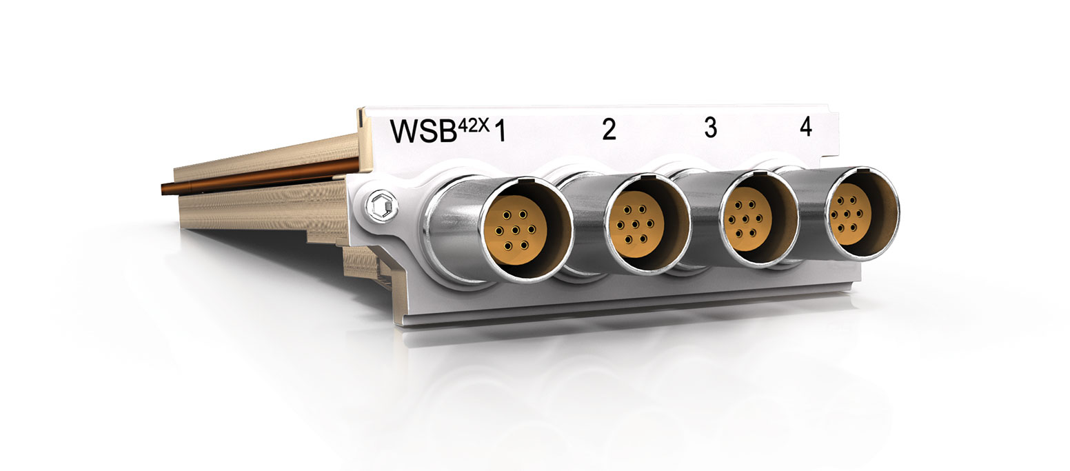
The WSB42X Module is used with AC and DC bridge measurements including strain gauges configured as full, half or quarter bridges and inductive displacement transducers (LVDT). The Module offers numerous software selectable features such as constant voltage (AC or DC) and constant current excitation (DC), bridge sensing, bridge completion resistors, shunt calibration, dynamic strain mode and ICP® sensor support. The bridge can be balanced on command or a previous balance value can be recalled.
Where used:
- Any strain gauge in quarter, half and full bridge, load cell and pressure transducer
- Inductive displacement transducer (LVDT)
- With any voltage source up to ±10 V in voltage input mode
- Current-excited sensors in 4-wire mode (full bridge or 1 external element, DC and AC)
- Current-excited sensors in 2-wire mode (dynamic strain only)
- With any ICP® based sensor commonly used to measure vibration, acceleration, force or pressure
WSB42X features:
- 4 channels
- 4 modes of operation
- ICP® mode with 4, 8 or 12 mA constant current at ±12 V excitation
-
Bridge voltage-excitation mode:
- 0-6 V (AC or DC) for 350 Ω full bridges
- 0-6 V (AC or DC) for 120 Ω and 350 Ω half or quarter bridges
- 0-4 V (AC or DC) for 120 Ω full bridges
- Bridge voltage-excitation mode: 8-10 V (DC) for 1 kΩ bridges
- 2 and 4 wire current-excitation strain mode: 4, 8 or 12 mA (DC)
- LVDT inductive displacement transducer mode (AC)
- Supports TEDS IEEE 1451.4 V0.9, V1.0 (Class 1 and 2)
- 24-bit resolution, 204.8 kSa/s sampling rate per channel, 100 kHz bandwidth
- < 0.2° @ 10 kHz phase accuracy when in similar range
- ±(10 mV, 100 mV, 1 V and 10 V) input ranges for all modes
- ≤ 10 kHz AC excitation
- Differential signal input, Differential voltage-excitation output and Differential sense input
- Full, half and quarter bridge configurations
- Internal half and quarter bridge
completion resistors for 120 Ω and
350 Ω bridge elements - Local and remote sense options
- 100 kΩ internal shunt calibration resistor
- Pre- and post-filter overflow monitoring
- Selectable low and high pass digital filters
- LEMO® 7-pin EHG.0B connectors
ALI25
The Industry’s first 5 MSa/s 24 bit Digitizer for Pyroshock applications. 2 Channels supporting Bridge, ICP® and Voltage Inputs and is equipped with a sophisticated anti-alias filtering system. Includes buffered analog output channels and advanced options for synchronization and triggering
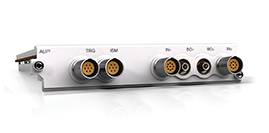
The ALI25 is a high-bandwidth Module designed for triggered/burst acquisition for Pyro-Shock / Mechanical Shock applications. Every channel is equipped with precise anti-alias filtering on the Signal and Sense lines, along with dedicated bridge signal conditioning. In addition, each channel features a 24-bit, 5 MSa/s ADC and a 21 MSa data buffer. Systems can be configured with 2 to over 1000 channels. Measurement Integrity and Sensor Status prior to an event is verified with continuous: pre-trigger monitoring, summarized signal information, and sensor fault detection. Built-in Signal Conditioning for bridge-type transducers and voltage signals. Constant voltage or current excitation is programmable for each channel. Each input channel has a buffered low-noise output channel for monitoring or acquiring sensor data via a secondary system. Measurements are triggerable by signal level and persistence, external events, data flow, or software command. This advanced set of triggering options supports multi-system synchronization and ensures event detection.
Where used:
- Acquisition of Pyro-Shock / Mechanical Shock events related to impact / shock, ballistics, and explosives test
- Bridge and Resistive Sensors that require 2-wire, 4-wire or 6-wire configurations
- High Voltage SubModule for external high-voltage signal conditioning used in power measurements
- Hopkinson Bar Testing
Related Cables, SubModules and Accessories
ALI25 features:
- 2 channels
- 4 modes of operation:
- Voltage input mode
- ICP® mode 4 mA to 20 mA with 30V compliance
-
Bridge input mode:
- 2-wire plus Shield, (Signal+, Signal-)
- 4-wire plus Shield, (Signal+, Signal-, Excitation+, Excitation-), targeting Pyro-Shock applications
- 6-wire plus Shield, (Signal+, Signal-, Excitation+, Excitation-, Sense+, Sense-)
- Constant Current Mode (CCM)
-
3 Stages of anti-aliasing (AA) filters:
- Analogue AA (AAA) Filtering: Provides a -0.1dB bandwidth of 2.5 MHz with minimal passband ripple and over 100 dB attenuation for high-frequencies
- Delta-Sigma ADC: Over-samples the signal 8 times and achieves a flat passband of up to 1.7 MHz, anti-aliasing ripple of less than ±0.00002dB, and stopband attenuation of 86dB
- FIR Filters: Ensure exceptional signal integrity with a maximum passband ripple of 0.0005 dB and minimum stopband attenuation exceeding 125 dB
- The ADC and FIR filters adapt to the ALI25’s decimation factor, providing optimized performance across varying data rates.
-
Input ranges:
- ±(5, 2.5, 1.25) V, ± (680, 340, 160, 80, 40, 20, 10) mV
- Slew Rate: >50 V/µs
- 21 M Samples per channel, 24-bit memory
- Differential input: input impedance 2 MΩ Differential, 1 MΩ to GND
- DC or AC coupling
- DC – 100 Hz, > 90 dB CMRR
-
Sense ADC:
- Continuous fault detection of the excitation lines to detect open / short circuits
- The ALI25 can support other applications that require more than the 4-wire Pyro-Shock applications.
-
Connectors:
- 9-pin LEMO® 0B.309 (one per input channel)
- Signal+, Signal-, Excitation+, Excitation-, Sense+, Sense-. TEDS (Class 1 & 2), AGND (REF GND), CGND
- Separate shield through the housing or pin of the breakout cable connector (9 pin LEMO® to D-Sub 15)
Cables:
- CS-ALI-A-DB15 500 (056K 500) - Breakout Signal Cable 500 mm (converts the 9-pin LEMO® connector to D-Sub 15)
- CS-ALI-A-DB15 2000 (056K 2000) - Breakout Signal Cable 2000 mm (converts the 9-pin LEMO® connector to D-Sub 15)
- CS-ALI-T-DB15 500 (058K 500) - Breakout Digital I/O Cable 500 mm (converts the 9-pin LEMO® connector to D-Sub 15)
- CS-ALI-T-DB15 2000 (058K 2000) - Breakout Digital I/O Cable 2000 mm (converts the 9-pin LEMO® connector to D-Sub 15)
- CS-ALI-T-2J 500 (068K 500) - Breakout Digital I/O Cable 500 mm (converts the 9-pin LEMO® connector to 2 BNC connectors)
- CS-ALI-T-2J 1000 (068K 1000) - Breakout Digital I/O Cable 1000 mm (converts the 9-pin LEMO® connector to 2 BNC connectors)
- CS-ALI-TF-5J 200 (069K 200) - Breakout Digital 5x Trigger I/O Cable 200 mm (converts the D-Sub 15 connector to 5 BNC connectors, Fanout cable for SM-ALI-TFCA-DB15)
- CS-ALI-A-9L-BNCP 2000 (076K 2000) - Breakout Signal Cable (Single-ended) 2000 mm (converts the 9-pin LEMO® connector to BNC connector)
- CS-ALI-A-DB15M-BNCP-2000 (077K 2000) - Breakout Signal Cable (Single-ended) 2000 mm (converts the D-Sub 15 connector of 056K to BNC connector)
- CS-ALI-A-SMB-BNCP 1000 (038K 1000) - Breakout Buffer Analog Output Cable 1000 mm (converts the SMB connector to BNC connector)
SubModules:
- SM-ALI-TFCA-DB15 500 - Trigger Fanout SubModule 500 mm (converts the 9-pin LEMO® connector to D-Sub 15)
- SM-ALI-SALI10 TYPE K, T - Thermocouple to Voltage SubModule with 290 kHz bandwidth (converts the D-Sub 15 for Thermocouple Type K and T)
- SM-ALI-SALI20 TYPE J - Thermocouple to Voltage SubModule with 290 kHz bandwidth (converts the D-Sub 15 for Thermocouple Type J)
- SM-ALI-SALI30-HS TYPE K,T - Thermocouple to Voltage SubModule with 1 MHz bandwidth (converts the D-Sub 15 for Thermocouple Type K and T)
Accessories:
- RM-ALI-NALI10-20 (PIPS) - 19 inch RackMount Kit to secure 20x D-Sub 15 connectors in one panel
- RM-ALI-NALI10-16 (PIPS) - 19 inch RackMount Kit to secure 16x D-Sub 15 connectors in one panel
- DQ04 | 06 Grounding Kit
MIC42X
Advanced 2 Channel Microphone, ICP® and Voltage Input Amplifier
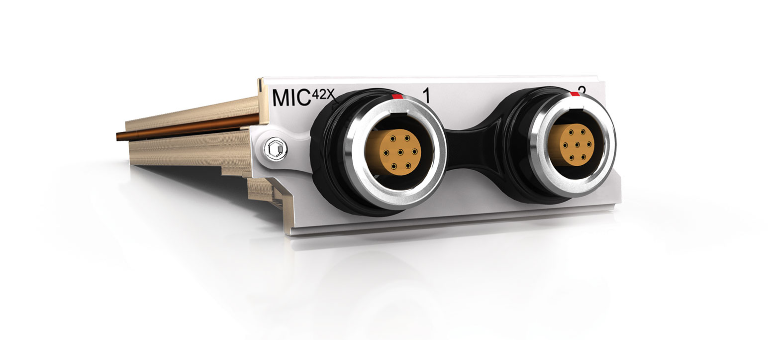
In addition to providing excellent performance for microphone measurements, the MIC42X Module also offers ICP® and voltage input modes.
Where used:
- With any 200 V or self-polarized microphones with pre-amplifier
- With any ICP® based sensor commonly used to measure vibration, acceleration, force and pressure
- With any voltage source up to ±12 V in voltage input mode
MIC42X features:
- 2 channels
- 3 input modes of operation:
- Microphone mode with 200 V or self-polarized microphone capsules with pre-amplifier
- ICP® mode with 4 mA, 8 mA or 12 mA constant current at 24 V excitation
- Voltage input mode with AC or DC coupling
- Supports TEDS IEEE 1451.4 V0.9, V1.0 (Class 1 and 2)
- 24-bit resolution, 204.8 kSa/s sampling rate per channel, 100 kHz bandwidth
- < 0.2° @ 10 kHz phase accuracy when in similar range
- ±(120 mV, 1.2 V and 12 V) input ranges
- ±14.5 V microphone pre-amplifier excitation voltage
- 0 or 200 V polarization output
- Microphone calibration output to inject test signals into microphone pre-amplifiers
- Exceptionally low distortion and noise design
- There are 3 distinctive input mode
options for both ICP® and voltage input modes:
- Differential or Balanced Float
- Single-Ended or Unbalanced Float
- Single-Ended or Unbalanced Ground
- Software-selectable connection of cable shield to Ground
- Short and open circuit cable monitoring
- Signal integrity circuit continuously monitors the input and disconnects sensitive circuits during overload conditions
- Pre-amplifier Excitation Short Circuit protection
- Pre- and post-filter overflow monitoring
- LEMO® 7-pin EGG.1B connectors
- Low power consumption
Related Cables:
- 044K – Converts LEMO® connector to BNC connector
ALO42S
4 Channel Voltage Output Source
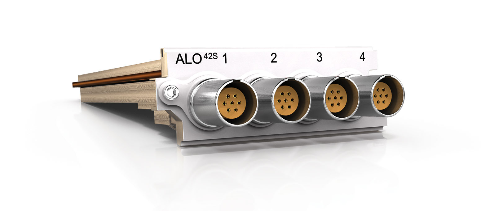
The ALO42S Module provides 4 independent output channels for the generation of analog signals. Each channel also incorporates Status Input and Output signals, enabling further communication with external equipment for applications such as test supervision or workflow control.
Where used:
- Excitation signals for shaker / modal testing
- Drive signals for acoustic testing
- Arbitrary analog signals to feed into other circuits requiring ±10 V static or dynamic signals
ALO42S features:
- 4 channels each with
- Analog Signal Output
- Module Status Output
- Device Under Control Status Input
- 5 V or 12 V DC Voltage Output
- 24-bit resolution, 204.8 kSa/s sampling rate per channel, 20 kHz 0.1 dB pass band flatness
- Low noise and distortion performance
- DC gain and offset stability
- ±10 V @ 30 mA output
- < 0.5° @ 10 kHz phase accuracy
- Provides Module Status Output
- Monitors Device Under Control Input
- Automatic safe shut down upon fault condition
- LEMO® 7-pin EHG.0B connectors
- 10 Ω output impedance
- Function generator output types:
- DC (-10 to 10 V)
- Sine (0 to 10 kHz, 20 Vpp, -360° to 360° relative phase)
- Square (0 to 10 kHz, 20 Vpp, -360° to 360° relative phase)
- Triangle (0 to 10 kHz, 10 Vpp, -360° to 360° relative phase)
- White noise (20 Vpp)
- Signal control:
- Enable / Disable Channel output
- Module Floating or Grounded Biasing
- Amplitude change time (0 to 3600 s; S-curve shaped ramp/fade from previous output to next
- Frequency / Phase change time (0 to 3600 s; S-curve shaped transition from previous output to new)
- Output voltage on Module Status pin:
- 0 V
- 5 V
- 12 V
Related SubModule:
- QBNC12 – Converts the LEMO® connector to 4 BNC connectors
CAN42S
Interface to 2 Controller Area Networks (CAN)
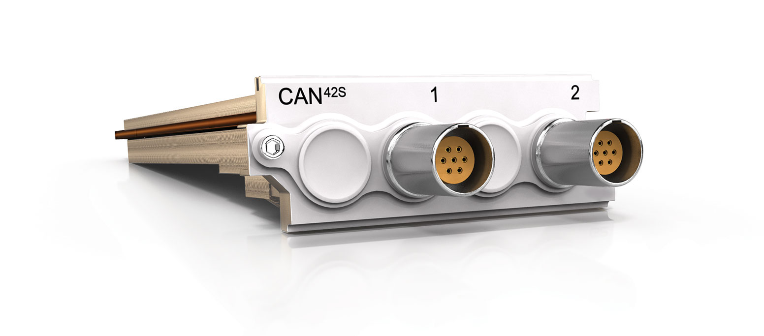
The CAN42S provides an interfaces to 2 CAN or CAN FD (CAN with Flexible Data-Rate) busses. CAN FD is an extension of the original CAN protocol which allows for higher data bandwidth. Messages received from CAN are time-stamped to synchronize their reception with analog and digital measurements from other Modules in the system. Fully implemented features include Participate Mode, Listen-Only Mode, Self-Reception of sent messages and Loopback Mode. The CAN42S Module provides independent channel filtering.
Where used:
- When monitoring CAN-based messages
- When controlling CAN-based devices
CAN42S features:
- 2 CAN / CAN FD Channels
- Conforms to ISO 11898-1:2015 (“ISO CAN FD”)
- Supports Arbitration Bit Rates from 50 kbit/s to 1000 kbit/s
- Supports Data Bit Rates from 500 kbit/s to 8000 kbit/s (single channel only), or 2000 kbit/s (both channels simultaneously)
- Supports Sample Point configuration for the arbitration phase
- Software selectable 120 Ω bus termination per Channel
- 2 modes of operation:
- Participate – actively acknowledges messages on the bus and sends messages
- Listen only – passively interprets messages that are sent between other nodes on the bus
- Loopback – forms an internal virtual bus that only receives its own sent messages
- Each CAN message received and accepted by the Module is time stamped in order to synchronize the received CAN messages with the rest of the measurement data
- Individually configurable identifier list per channel to provide acceptance filtering for all CAN messages received from the CANbus
- Individually configurable CAN message transmission
- Each channel has protection against ESD and other harmful transients
- LEMO® 7-pin EHG.0B connectors
Related SubModule:
- CANC10 – Provides an interface to a D-sub 9 connector (to a CANbus network)
GPS42S
Internal GPS Interface
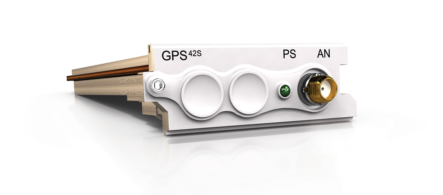
The GPS42S provides accurate GPS time and position data to QuantusSeries systems. Accurate timing information is in the form of a synchronized pulse logical signal.
The Module can also be used for synchronization purposes. The GPS42S Module provides the System controller with the synchronized pulse signal to align its internal clock. Systems with this capability are able to synchronize with one another without limitations as to their position or the total number of systems.
Where used:
- Synchronizing numerous channels over multiple Systems
- When requiring accurate time and position information
GPS42S features:
- Internal GPS channel
- NMEA and UBX Protocols available
- 4 Hz position updates
- Time-stamping for received GPS time and position data to 5 µs resolution
- 3.3 V antenna voltage
- Position accuracy 2.5 m
- 1 channel SMA connector for antenna
- Receiver type: 56 channels GPS L1C/A SBAS L1C/A QZSS L1C/A GALILEO E1B/C