![]()
USER MANUAL
![]()
USER MANUAL
![]()
This equipment measures high-speed analog and digital signals in laboratory or mobile environments. It may also be used in other areas, for example when troubleshooting or performing field tests. The use of the DECAQ measurement system requires an understanding of the measurement chain and signal analysis.
Even though the DECAQ has been designed to withstand rough handling, it is a sensitive and complex electronic instrument and must be handled with care.
The DECAQ must be powered down for 30 seconds before any Module or Board can be inserted or removed. The DECAQ hardware is not hot-swappable.
Care has been taken to provide reasonable ESD protection. However, all DECAQ components are sensitive to ESD and may be damaged by an ESD discharge.
To avoid damaging the DECAQ, antistatic precautions must be followed. This is especially important when swapping Modules. However, care must also be taken when swapping combined System Controller and Power Supply boards, Signal Conditioning boards or Synchronization Engines. Antistatic precautions are advisable when connecting cables or sensors to Modules.
Precautions include:
Do not use a damaged power supply, cable or any other DECAQ component.
The DECAQ may not be operated or stored in flammable environments (fumes, gasses, liquids, etc.), excessively harsh environments (corrosive, ambient temperature above 50 °C, radioactive, hydraulic fluid, etc.), or excessively damp environments.
The radiated output power of the DECAQ is within acceptable radio frequency exposure limits and is intended to be used 300 mm away from a human operator.
Depending on the configuration, the DECAQ may become heavy and could pose a danger if not stored or transported in a responsible manner. Please use the handle provided. When using the removable handle, ensure it is properly installed and the locking mechanisms are engaged.
Mecalc supports environmentally sound recycling. Recycle or dispose of DECAQ Batteries through a reputable service provider or contact your supplier (Mecalc Representative or Channel Partner) for assistance. This is also applicable to any other broken or unused components.
The products in this manual do not contain any mercury or mercury compounds.
The products in this manual do not contain any substances listed as Class I or Class II specified chemical substances under the Japan Chemical Substances Control Law (CSCL).
Mecalc believes in ethical and responsible practices and is committed to promoting economic, environmental and social justice at all levels of our supply and manufacturing processes.
As part of this commitment, we:
Support the “OECD Due Diligence Guidance for Responsible Supply Chains of Minerals from Conflict-Affected and High-Risk Areas”
Have conducted a Conflict Mineral report using the Responsible Minerals Initiative’s Conflict Minerals Reporting Template (CMRT) and Extended Mineral Reporting Template (EMRT)
Require all our suppliers to source minerals exclusively from smelters or refiners that comply with principles highlighted in the “OECD Due Diligence Guidance for Responsible Supply Chains of Minerals from Conflict-Affected and High-Risk Areas”
The DECAQ measurement frontend is classified as “a digital device used exclusively as industrial, commercial, or medical test equipment”. Therefore, according to CFR47 section 15.103 the DECAQ measurement frontend is exempt from the specific technical standards in CFR47 part 15. Even though the starred combinations have not been explicitly certified for FCC/IC compliance, Mecalc did endeavour to have the device meet the specific technical standards. All DECAQ measurement frontends may therefore be used in the USA or Canada provided that according to CFR47 section 15.103, “the operator of the exempted device shall be required to stop operating the device upon a finding by the Commission or its representative that the device is causing harmful interference”.
The WLAN Module used in the DECAQ has been pre-certified for use in Japan and South Korea.
The products described in this manual are not designed, developed, or intended for military use. They are not included on the United States Munitions List (USML) as defined under the International Traffic in Arms Regulations (ITAR), 22 CFR Parts 120–130.
All products are classified as Commercial Off-The-Shelf (COTS) items. Additionally, these products are regulated under the Export Administration Regulations (EAR) and are classified under Export Control Classification Number (ECCN) 3A992.a. This classification applies to general-purpose electronic devices intended for civilian and industrial applications.
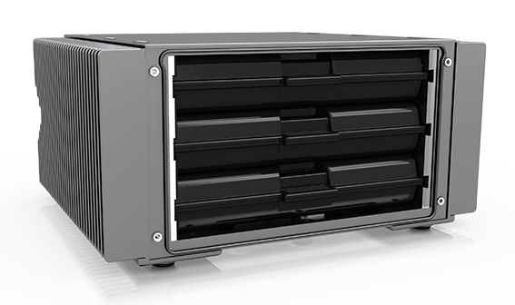
DECAQ systems are compact data acquisition systems which measure high-speed analog and digital signals. Designed for portable measurement, troubleshooting, field testing and complex laboratory applications, DECAQ systems are capable of housing up to 216 channels in a single chassis. Each DECAQ system can securely connect, communicate and be controlled using either the User Interface, a laptop or smart device, as well as to store data for later playback.
A typical user will have an understanding of measurement chain and signal analysis.
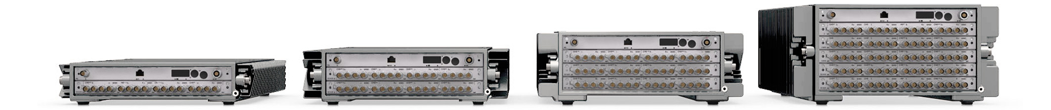
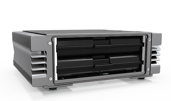
The DECAQ comes in 4 chassis sizes, namely the DECAQ 2-slot, 3-slot, 4-slot and 6-slot chassis. This section shows views for each chassis size.
Rack Mount versions of the DECAQ Mainframes are shown in section 5.
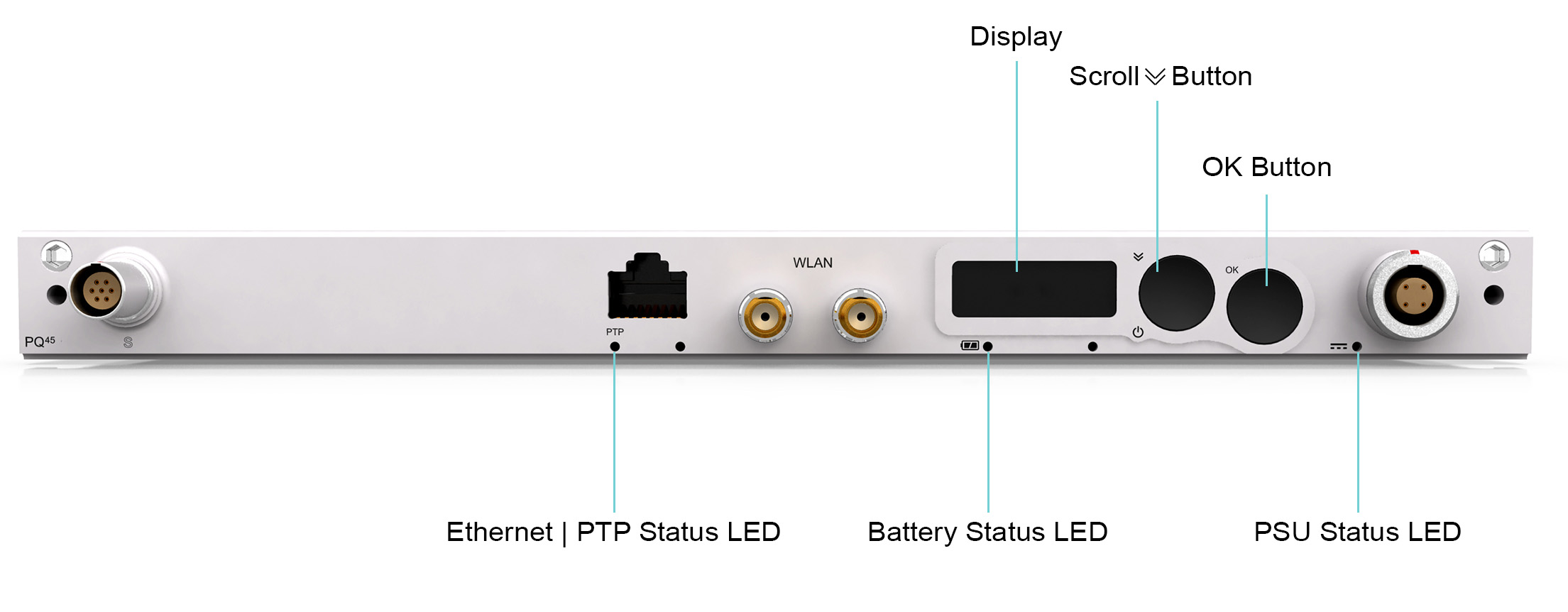
This section highlights front view features common to all systems.
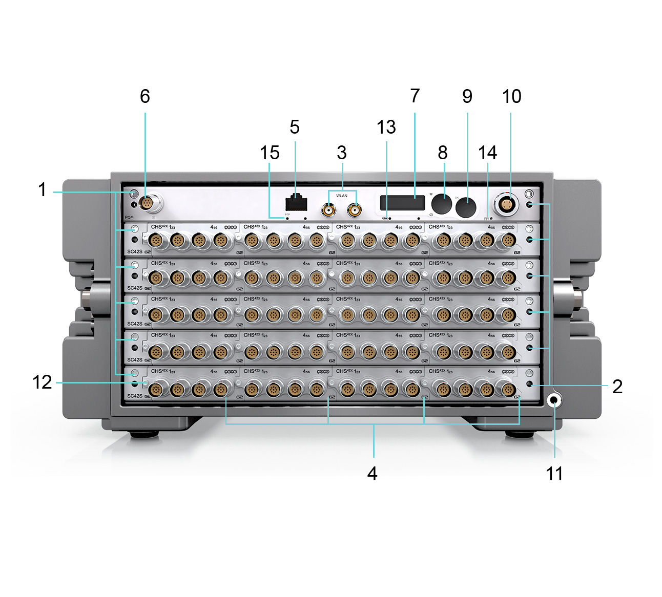
1. Extraction Jacking Screw To remove the board from the chassis during system maintenance, tighten the extraction jacking screw until the board ejects.
2. Portal for Thermal Expanders Ensure the thermal expanders have been properly fastened before conducting measurements. See Handling Guidelines for Effective Cooling for more information.
3. Built-in Wi-Fi Antenna Connectors Reverse Polarity SMA Female connectors for IEEE 802.11 a/b/g/n WLAN communication. The antenna should have a Reverse Polarity SMA Male connector.
4. QModule slots Featured QModule: Slot 2 CHS42X:6 Channel Charge or ICP®/IEPE and Voltage Input Amplifier See Measure: Signal Conditioning for more information.
5. Ethernet (Ethernet / PTP) Ethernet 1000BASE-T PTP (Precision Time Protocol) IEEE 1588-2008 PTP synchronization over Ethernet. See Synchronization for more information.
6. S-Port Connect to the ATTOQs via the S-Port.
7. User Interface Display Receive system information and execute commands via the User Interface. See Navigating the DECAQ’s User Interface Display for more information.
8. User Interface Scroll Button Use
the Scroll Button
( )
to switch on the DECAQ and scroll through User
Interface menu options. See Navigating the DECAQ’s
User Interface Display for more information.
)
to switch on the DECAQ and scroll through User
Interface menu options. See Navigating the DECAQ’s
User Interface Display for more information.
9. User Interface OK Button Confirm User Interface menu option selections using the OK Button. See Navigating the DECAQ’s User Interface Display for more information.
10. Power LEMO® Power the DECAQ with an external power source via the Power LEMO®. See Power for more information.
11. Earth Terminal Beware of ground loops as the system is earthed via the Mean Well power supply. Consider connecting the Earth Terminal to the building safety earth if there is any risk of electrical shock in the testing environment. It can be used to provide a ground reference for analog signal measurements, if appropriate settings are applied to the relevant QModule channels. It can also be used in some cases to decrease noise on analog signals.
12. QModule Jacking Screw Insert and remove QModules using a Jacking Screw. See Inserting and Removing QModules for more information.
13. Battery Status LED Provides information about the internal battery to the User.
14. Power Supply Status LED Provides information about the power supply to the User.
15. Ethernet / PTP Status LED Synchronize DECAQ systems with PTP (Precision Time Protocol) See Synchronization for more information.
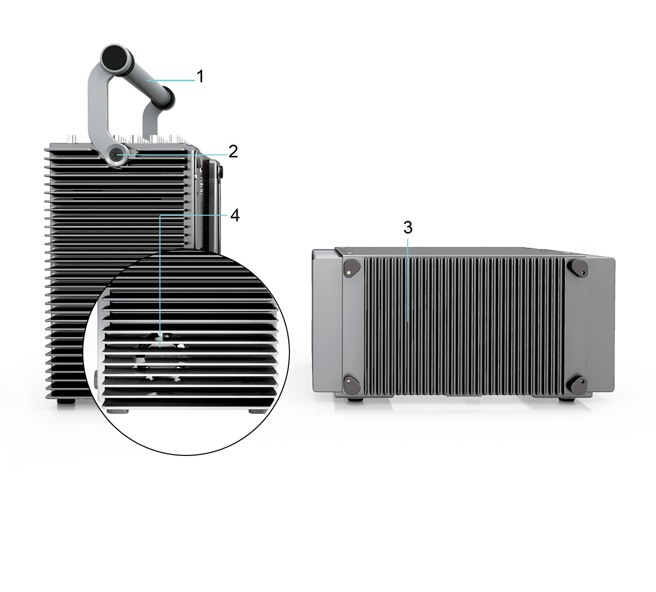
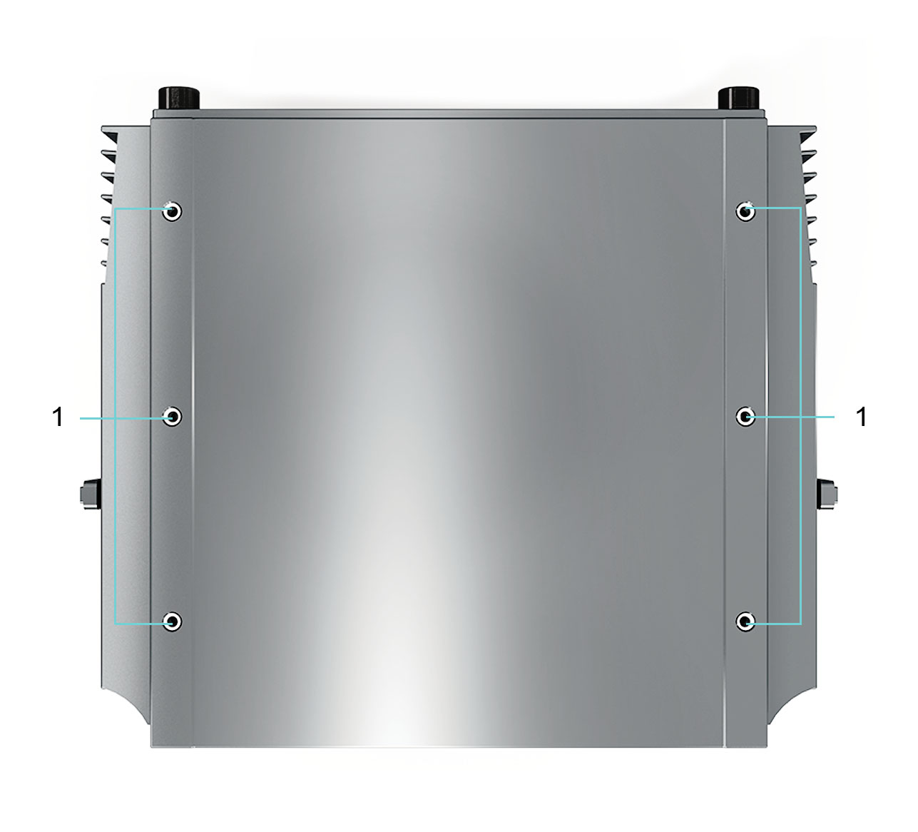
The following section provides the Top, Side and Bottom Views of the DECAQ 2-slot.
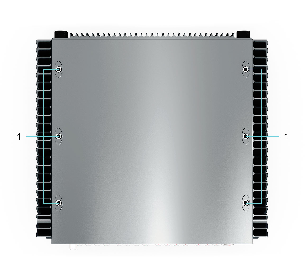
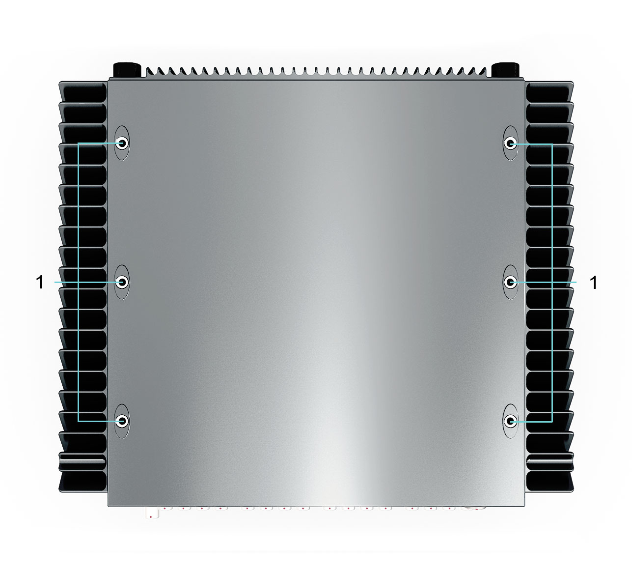
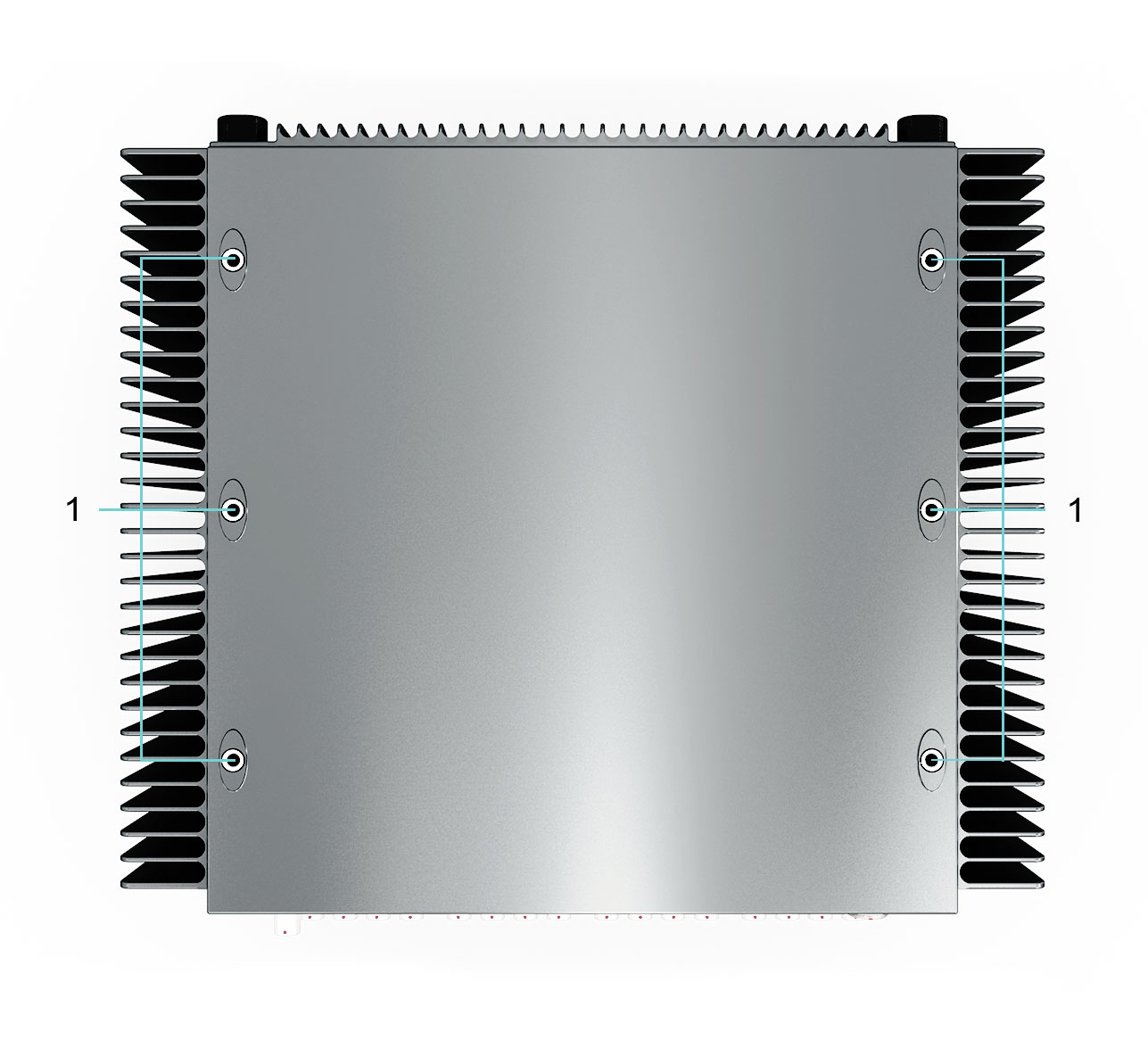
1. Fastening Inserts Fasten your chassis onto a surface using the fastening inserts.
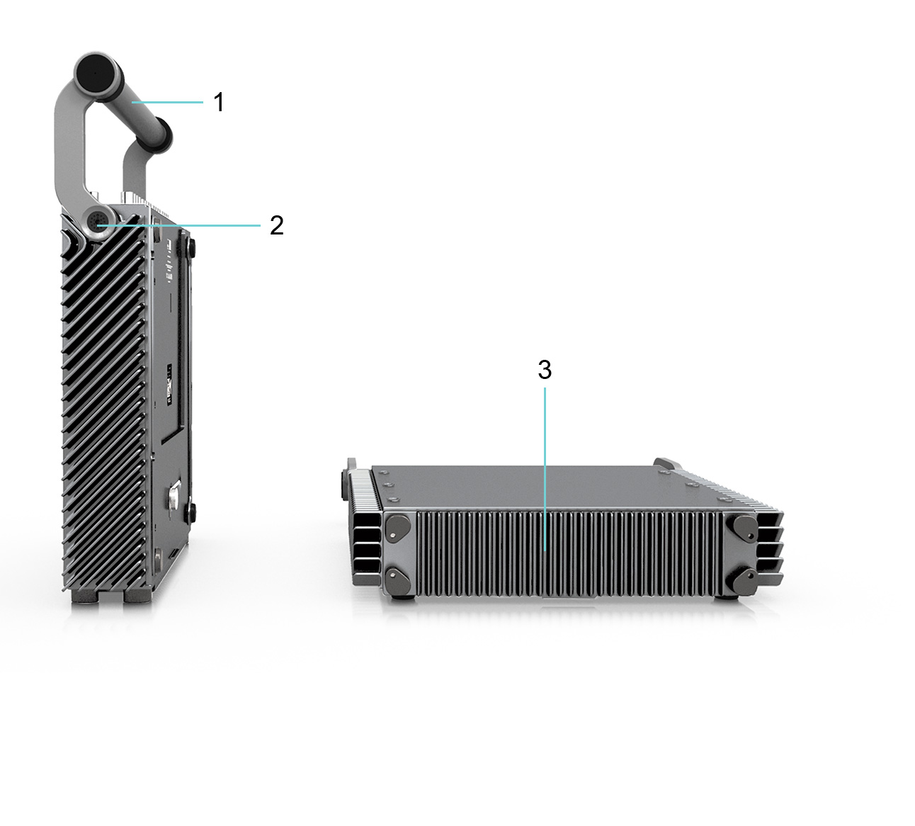
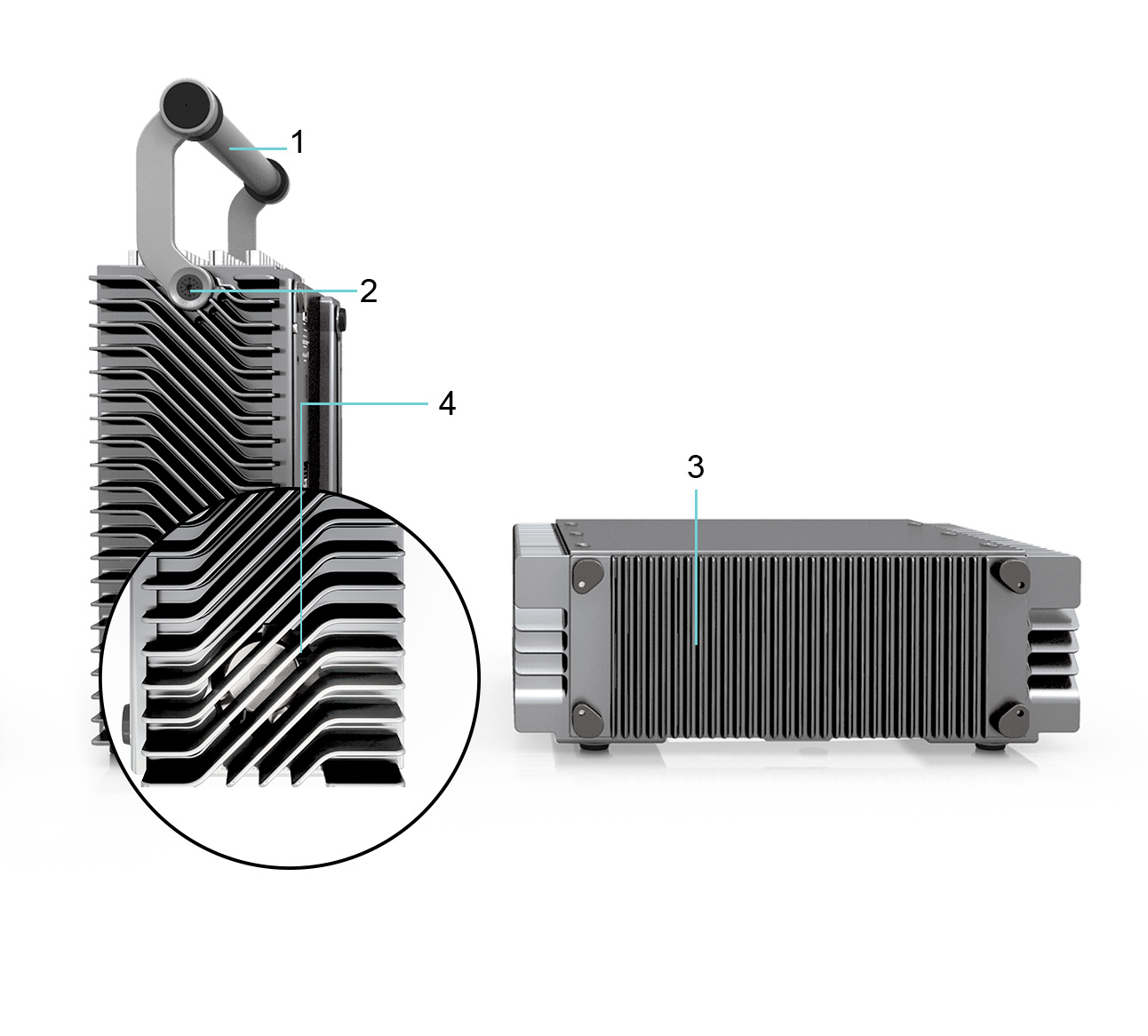
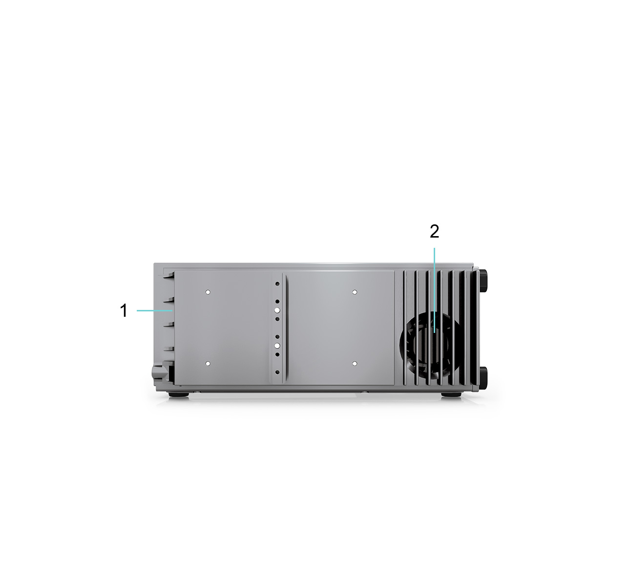
1. Handle For simplified handling, use the handle when carrying the chassis.
2. Handle Adjustment Button To adjust your handle, press down on the Handle Adjustment Button. Move the handle from 0° to 45°, 90°, 135° and finally 180°. Once the handle reaches any one of the four settings, it will lock into that position until the button is pressed in to adjust the handle again. Please ensure the Handle Adjustment Button is locked before picking up the system with the handle.
3. Fins Fins provide conduction cooling for the system chassis. Keep the chassis fins unobstructed while conducting a measurement. See Handling Guidelines for Effective Cooling for more information.
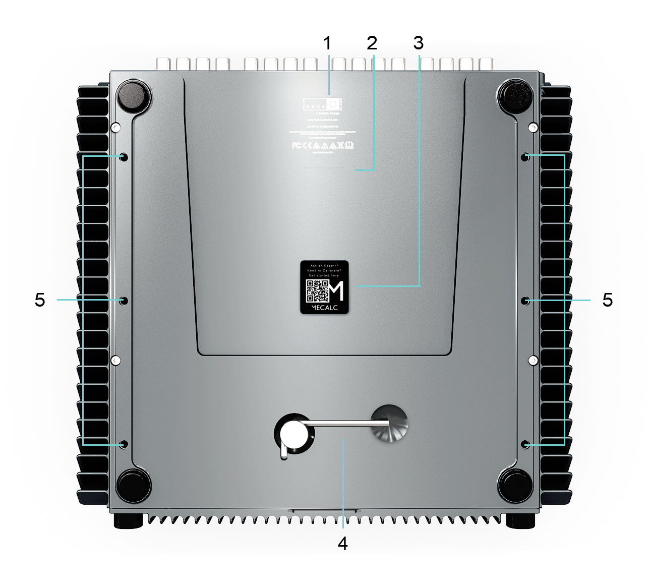
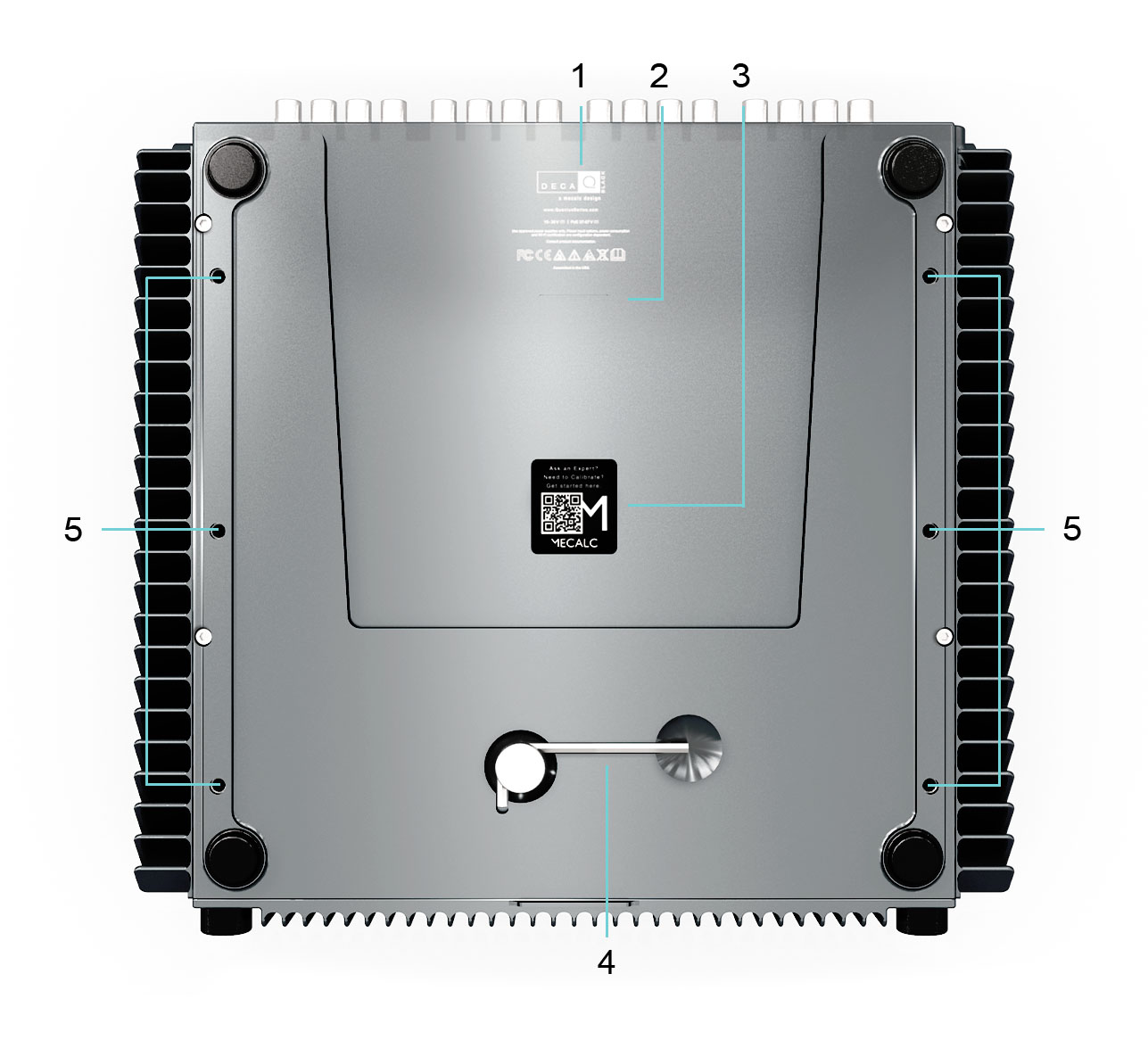
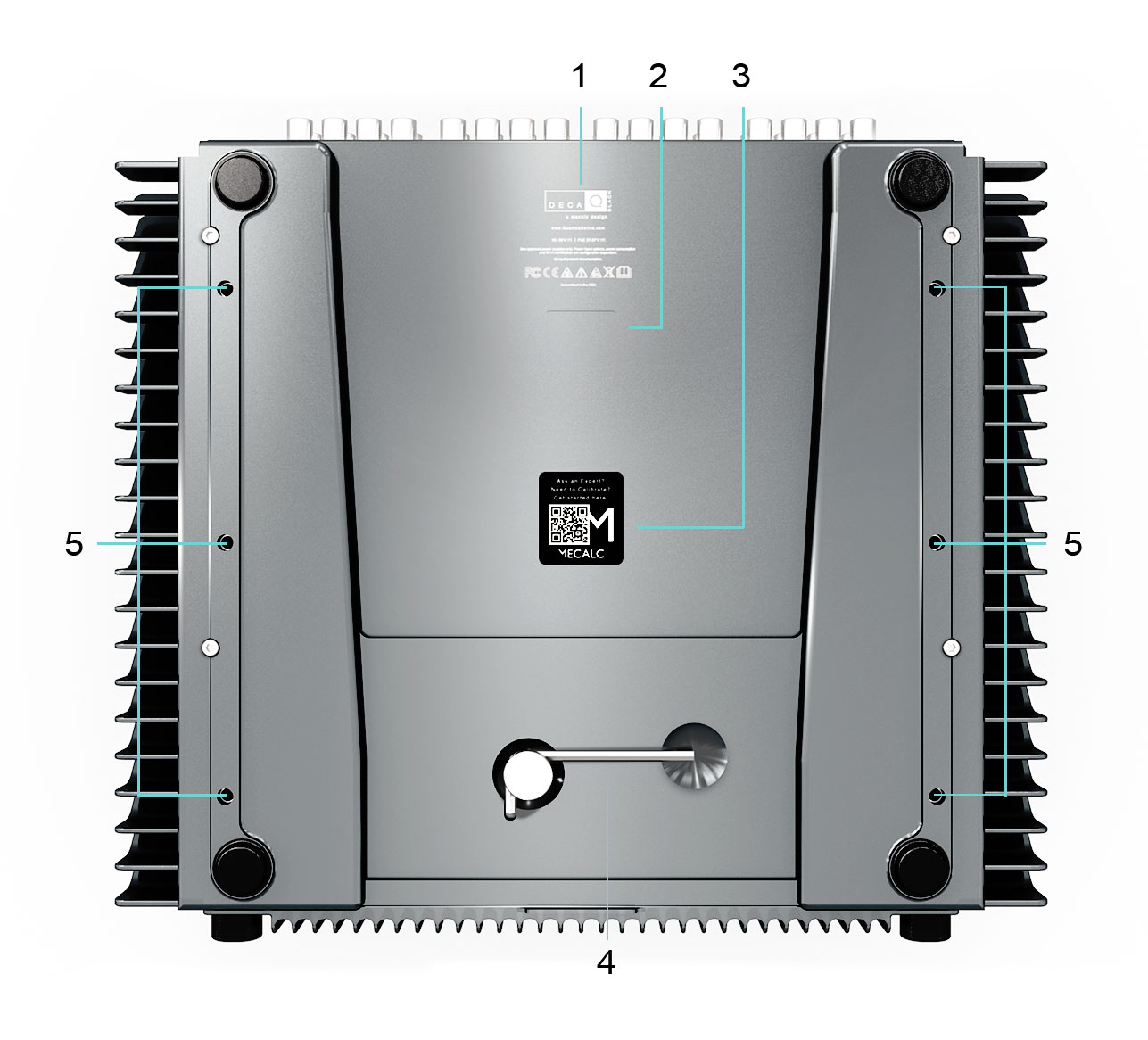
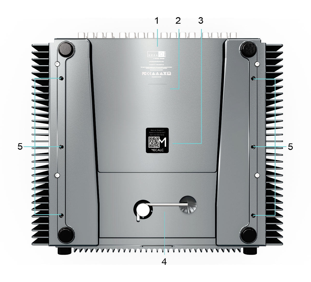
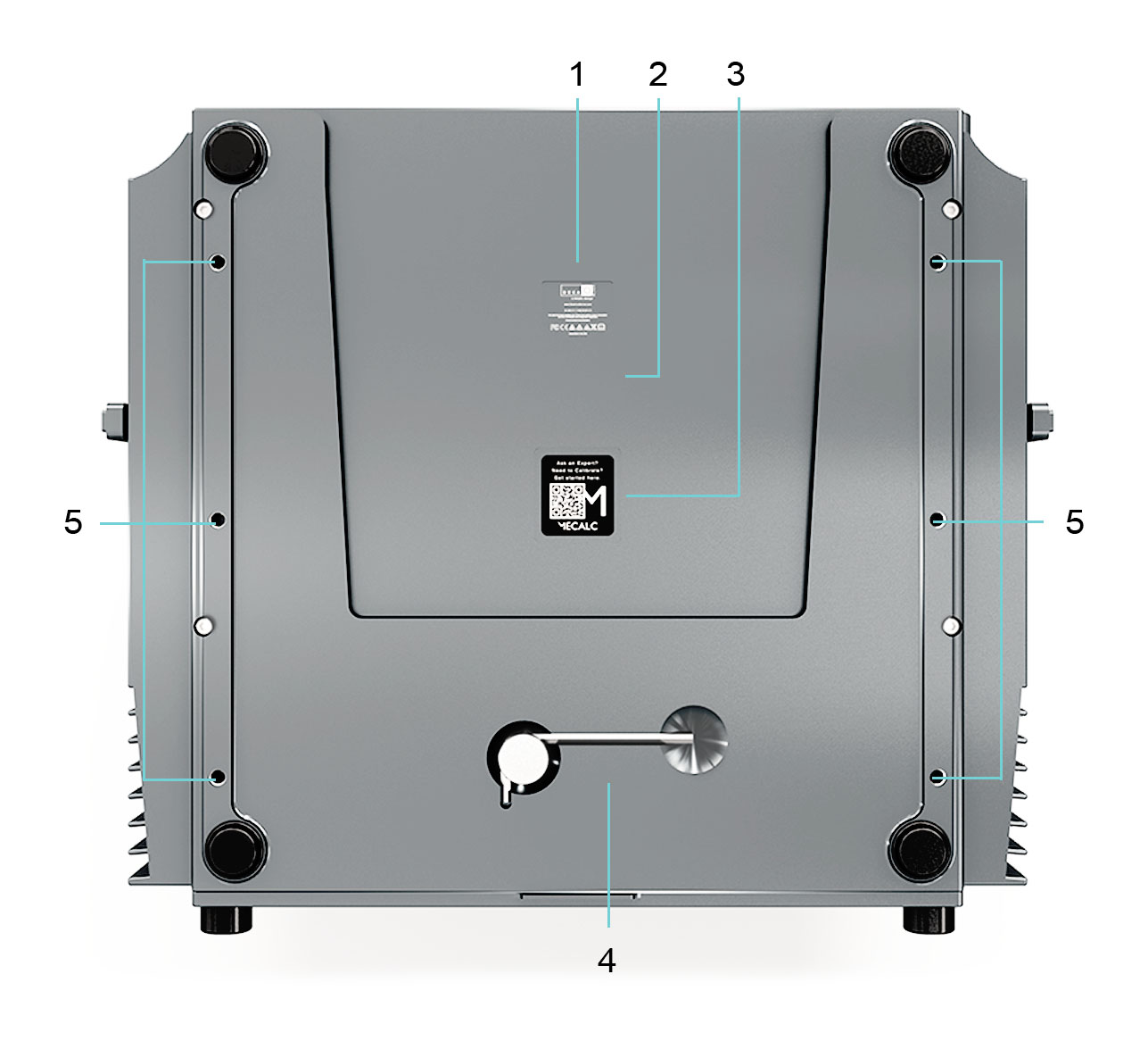
1. Product Identifier The Product Identifier includes certifications and warnings related to the use of the DECAQ.
2. Serial Number Label The Serial Number / Barcode Label of each DECAQ is found on its base. This identifier allows our Product Experts to access information specific to your device in order to provide valuable support services.
3. Mecalc or Partner Label The Mecalc or Partner Label provides a QR code that lets the User access support information such as User Guides.
4. HEX key The HEX key is used to gain access to the rear cover to insert/remove batteries.
5. Fastening Inserts Fasten your chassis onto a surface using the fastening inserts.
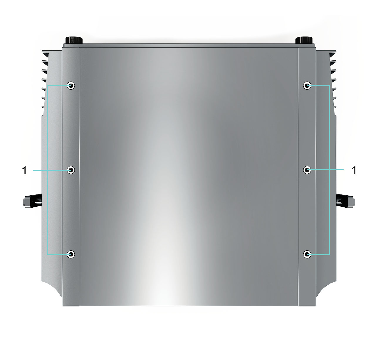
The following section provides the Top, Side and Bottom Views of the DECAQ 3-slot.
1. Fastening Inserts Fasten your chassis onto a surface using the fastening inserts.
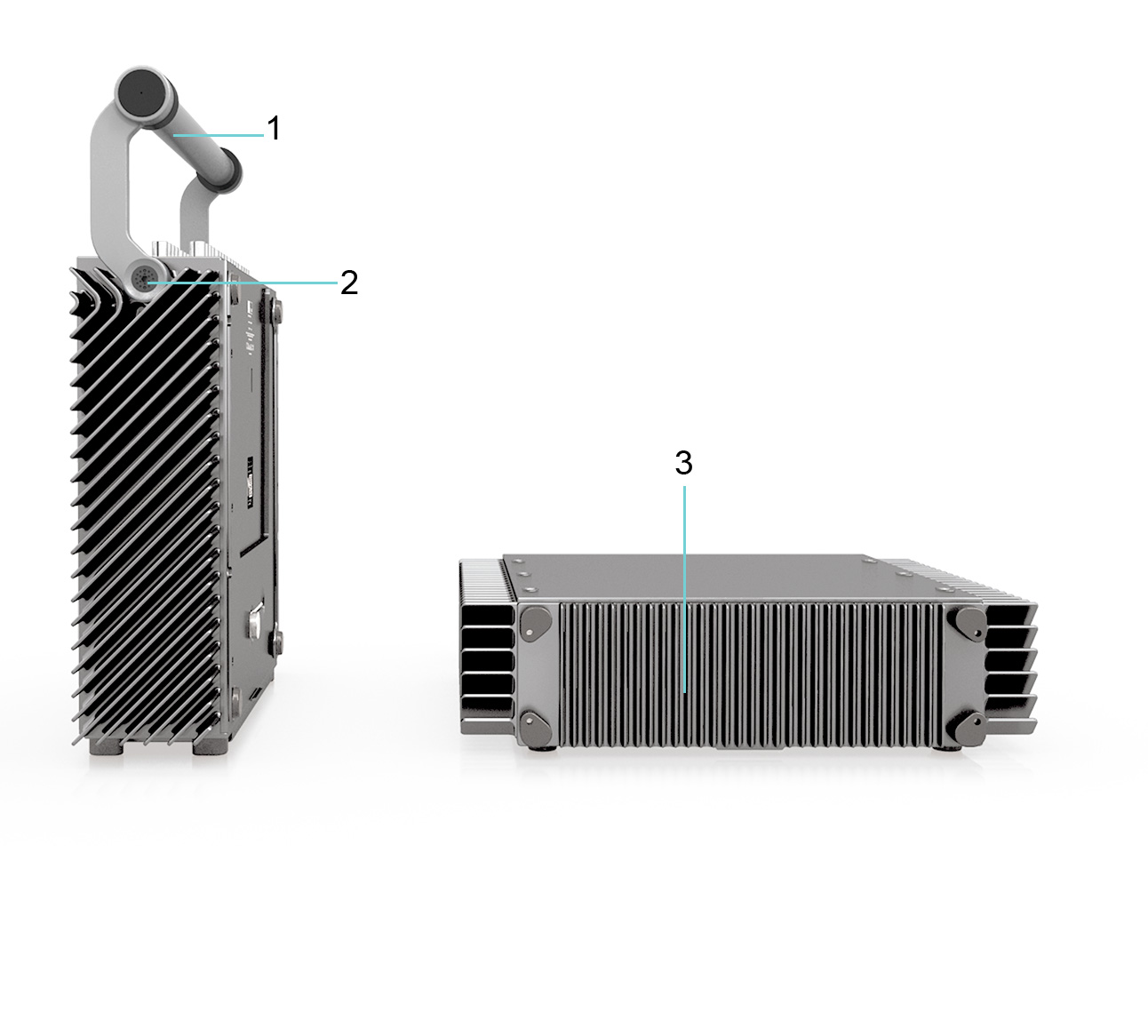
1. Handle For simplified handling, use the handle when carrying the chassis.
2. Handle Adjustment Button To adjust your handle, press down on the Handle Adjustment Button. Move the handle from 0° to 45°, 90°, 135° and finally 180°. Once the handle reaches any one of the four settings, it will lock into that position until the button is pressed in to adjust the handle again. Please ensure the Handle Adjustment Button is locked before picking up the system with the handle.
3. Fins Fins provide conduction cooling for the system chassis. Keep the chassis fins unobstructed while conducting a measurement. See Handling Guidelines for Effective Cooling for more information.
1. Product Identifier The Product Identifier includes certifications and warnings related to the use of the DECAQ.
2. Serial Number Label The Serial Number / Barcode Label of each DECAQ is found on its base. This identifier allows our Product Experts to access information specific to your device in order to provide valuable support services.
3. Mecalc or Partner Label The Mecalc or Partner Label provides a QR code that lets the User access support information such as User Guides.
4. HEX key The HEX key is used to gain access to the rear cover to insert / remove batteries.
5. Fastening Inserts Fasten your chassis onto a surface using the fastening inserts.
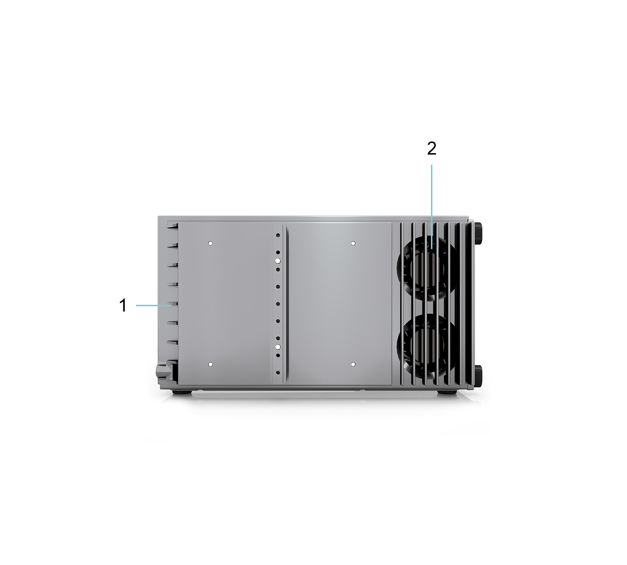
The following section provides the Top, Side and Bottom Views of the DECAQ 4-slot.
1. Fastening Inserts Fasten your chassis onto a surface using the fastening inserts.
1. Handle For simplified handling, use the handle when carrying the chassis.
2. Handle Adjustment Button To adjust your handle, press down on the Handle Adjustment Button. Move the handle from 0° to 45°, 90°, 135° and finally 180°. Once the handle reaches any one of the four settings, it will lock into that position until the button is pressed in to adjust the handle again. Please ensure the Handle Adjustment Button is locked before picking up the system with the handle.
3. Fins Fins provide conduction cooling for the system chassis. Keep the chassis fins unobstructed while conducting a measurement. See Handling Guidelines for Effective Cooling for more information.
4. Fans Fans provide cooling for the system’s chassis. Keep the fan intake unobstructed while conducting a measurement. See Handling Guidelines for Effective Cooling for more information.
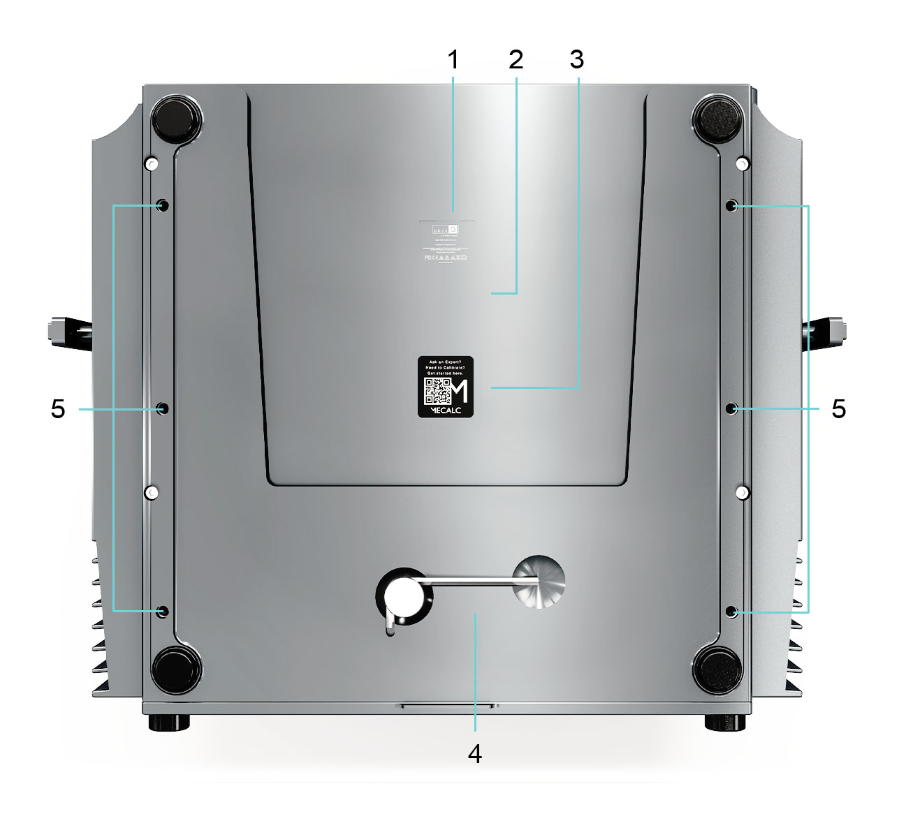
1. Product Identifier The Product Identifier includes certifications and warnings related to the use of the DECAQ.
2. Serial Number Label The Serial Number / Barcode Label of each DECAQ is found on its base. This identifier allows our Product Experts to access information specific to your device in order to provide valuable support services.
3. Mecalc or Partner Label The Mecalc or Partner Label provides a QR code that lets the User access support information such as User Guide.
4. HEX key The HEX key is used to gain access to the rear cover to insert / remove batteries.
5. Fastening Inserts Fasten your chassis onto a surface using the fastening inserts.
The following section provides the Top, Side and Bottom Views of the DECAQ 6-slot.
1. Fastening Inserts Fasten your chassis onto a surface using the fastening inserts.
1. Handle For simplified handling, use the handle when carrying the chassis.
2. Handle Adjustment Button To adjust your handle, press down on the Handle Adjustment Button. Move the handle from 0° to 45°, 90°, 135° and finally 180°. Once the handle reaches any one of the four settings, it will lock into that position until the button is pressed in to adjust the handle again. Please ensure the Handle Adjustment Button is locked before picking up the system with the handle.
3. Fins Fins provide conduction cooling for the system chassis. Keep the chassis fins unobstructed while conducting a measurement. See Handling Guidelines for Effective Cooling for more information.
4. Fans Fans provide cooling for the system’s chassis. Keep the fan intake unobstructed while conducting a measurement. See Handling Guidelines for Effective Cooling for more information.
1. Product Identifier The Product Identifier includes certifications and warnings related to the use of the DECAQ.
2. Serial Number Label The Serial Number / Barcode Label of each DECAQ is found on its base. This identifier allows our Product Experts to access information specific to your device in order to provide valuable support services.
3. Mecalc or Partner Label The Mecalc or Partner Label provides a QR code that lets the User access support information such as User Guide.
4. HEX key The HEX key is used to gain access to the rear cover to insert / remove batteries.
5. Fastening Inserts Fasten your chassis onto a surface using the fastening inserts.
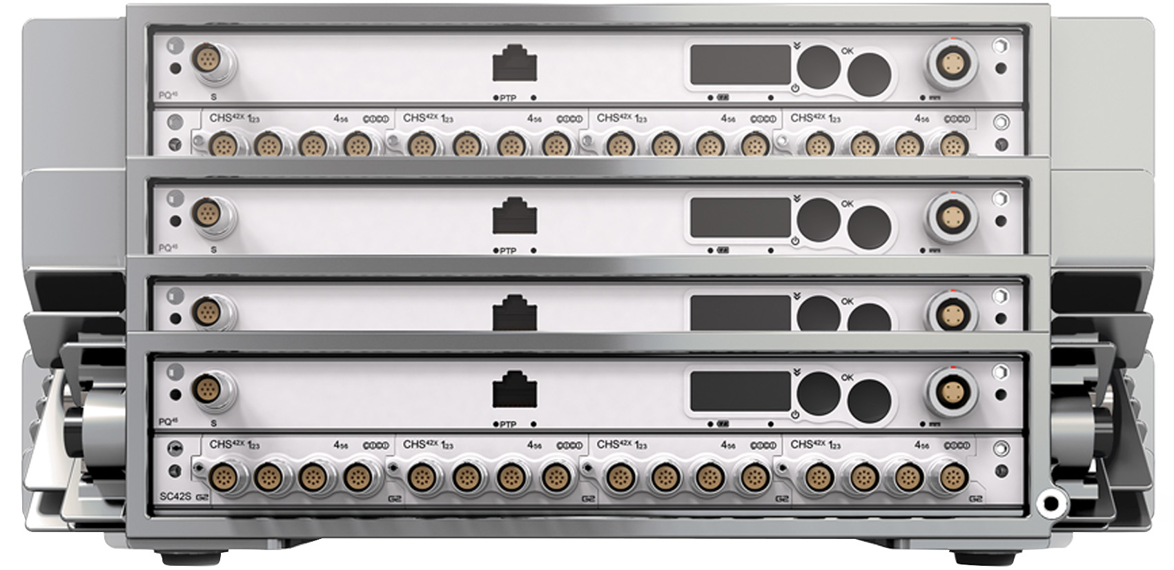
The DECAQ L chassis has been designed to fit into a 19” rack for stationary use in a laboratory. The DECAQ L chassis has improved airflow with air being blown through vents at both sides. There are no fins on the sides or the rear of the DECAQ L chassis.
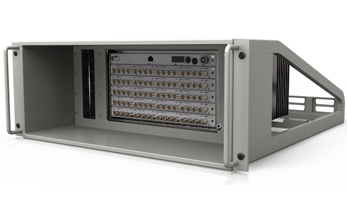
This section highlights front view features common to all L systems.
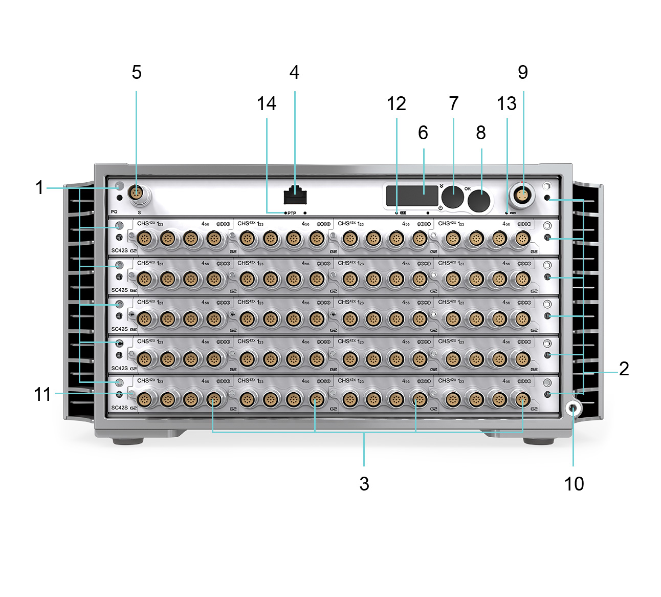
1. Extraction Jacking Screw To remove the board from the chassis during system maintenance, tighten the extraction jacking screw until the board ejects.
2. Portal for Thermal Expanders Ensure the thermal expanders have been properly fastened before conducting measurements. See Handling Guidelines for Effective Cooling for more information.
3. QModule slots Featured QModule: Slot 2 CHS42X:6 Channel Charge or ICP®/IPE and Voltage Input Amplifier See Measure: Signal Conditioning for more information.
4. Ethernet (Ethernet / PTP) Ethernet 1000BASE-T PTP (Precision Time Protocol) IEEE 1588-2008 PTP synchronization over Ethernet. See Synchronization for more information.
5. S-Port Connect to the ATTOQs via the S-Port.
6. User Interface Display Receive system information and execute commands via the User Interface. See Navigating the DECAQ’s User Interface Display for more information.
7. User Interface Scroll Button
()
Use the Scroll Button to switch on the DECAQ L and scroll through the User Interface menu options. See Navigating the DECAQ’s User Interface Display for more information.
8. User Interface OK Button Confirm User Interface menu option selections using the OK Button. See Navigating the DECAQ’s User Interface Display for more information.
9. Power LEMO® Power the DECAQ L with an external power source via the Power LEMO®. See Power for more information.
10. Earth Terminal Beware of ground loops as the system is earthed via the Mean Well power supply. Consider connecting the Earth Terminal to the building safety earth if there is any risk of electrical shock in the testing environment. It can be used to provide a ground reference for analog signal measurements, if appropriate settings are applied to the relevant QModule channels. It can also be used in some cases to decrease noise on analog signals.
11. QModule Jacking Screw Insert and remove QModules using a Jacking Screw. See Inserting and Removing QModules for more information.
12. Battery Status LED Provides information about the internal battery to the User.
13. Power Supply Status LED Provides information about the power supply to the User.
14. Ethernet / PTP Status LED Synchronize DECAQ systems with PTP (Precision Time Protocol) See Synchronization for more information.
The following section provides the Top, Side and Bottom Views of the DECAQ L 4-slot.
1. Fastening Inserts Fasten your chassis onto a surface using the fastening inserts.
1. Vents Vents provide conduction cooling for the system chassis. Keep the chassis vents unobstructed while conducting a measurement. See Handling Guidelines for Effective Cooling for more information.
2. Fans Fans provide cooling for the system’s chassis. Keep the fan intake unobstructed while conducting a measurement. See Handling Guidelines for Effective Cooling for more information.
1. Product Identifier The Product Identifier includes certifications and warnings related to the use of the DECAQ L.
2. Serial Number Label The Serial Number / Barcode Label of each DECAQ L is found on its base. This identifier allows our Product Experts to access information specific to your device in order to provide valuable support services.
3. Mecalc or Partner Label The Mecalc or Partner Label provides a QR code that lets the User access support information such as User Guide.
4. HEX key The HEX key is used to gain access to insert/remove batteries.
5. Fastening Inserts Fasten your chassis onto a surface using the fastening inserts.
The following section provides the Top, Side and Bottom Views of the DECAQ 6-slot.
1. Fastening Inserts Fasten your chassis onto a surface using the fastening inserts.
1. Vents Vents provide conduction cooling for the system chassis. Keep the chassis vents unobstructed while conducting a measurement. See Handling Guidelines for Effective Cooling for more information.
2. Fans Fans provide cooling for the system’s chassis. Keep the fan intake unobstructed while conducting a measurement. See Handling Guidelines for Effective Cooling for more information.
1. Product Identifier The Product Identifier includes certifications and warnings related to the use of the DECAQ.
2. Serial Number Label The Serial Number / Barcode Label of each DECAQ is found on its base. This identifier allows our Product Experts to access information specific to your device in order to provide valuable support services.
3. Mecalc or Partner Label The Mecalc or Partner Label provides a QR code that lets the User access support information such as User Guide.
4. HEX key The HEX key is used to gain access to insert/remove batteries.
5. Fastening Inserts Fasten your chassis onto a surface using the fastening inserts.
The DECAQ complies with EMC directives.
When connecting cables, sensors or third-party devices to the DECAQ, electromagnetic noise could be introduced into the measurement.
Recommendations for good measurement practice include:
The DECAQ systems use customized power cables to ensure they operate at their optimum level. Using a third-party cable is highly discouraged, as this may damage your system. Contact your supplier for more information about which cable is best suited for your measurement configuration.
DECAQ systems operate within a range of 10 - 30 VDC voltage. When running the DECAQ from lower voltages, the resulting increased current could cause power cables and connectors to heat up. A lowered supply voltage increases the current flowing through the resistance of the cable and connector, resulting in a quadratic rise in temperature.
When powering larger DECAQ systems, it is therefore recommended to:
When switching off your system, make sure it is being powered down using either the Web Server or the User Interface Buttons on the chassis front panel. Switching off the system by merely disconnecting the power supply could result in permanent hardware damage.
Additionally, avoid disconnecting the power supply if a battery is not present. The system’s battery power will ensure the protection of your hardware and/or recorded data if the power supply gets disconnected. If you need to switch off the system while it is running on battery power only, please do so using the Web Server or User Interface Buttons (see above).
| Warning |
|---|
| Do not switch off or reset your DECAQ system while it is booting or while a firmware upgrade is in progress. This could permanently damage the system. Wait for the display to show ‘IDLE’, ‘LIVE’, ‘REC’, or ‘FAIL’ before continuing to operate on the system. |
The following table provides information which serves as a guideline when choosing the appropriate power cable for your external power connection:
| Termination | Max Current | Length | Name |
|---|---|---|---|
| Mean Well AC-DC Adapters | 15.0 A | 1.0 m | 230K |
| Mean Well AC-DC Adapters | 15.0 A | Variable | 231K |
| Banana Plugs | 15.0 A | 2.0 m | 213K |
| Cigarette Plugs | 15.0 A | 2.0 m | 214K |
| Banana Plugs | 20.0 A | 2.0 m | 216K |
| Banana Plugs | 20.0 A | Variable | 221K |
Suggested power cables for different system configurations
| Power Source | Power Source | Power Source | Power Source | Power Source | Power Source | |
|---|---|---|---|---|---|---|
| Signal Conditioning and Channel Count | Bench / Battery | Bench / Battery | Cigarette Lighter Socket | Mean Well (15 V) Part Numbers: GST160A15-R7B GST220A15-R7B | Mean Well (24 V) Part Number: GST120A24-R7B GST220A24-R7B | TDK Lambda (26 V, 260 W) Part Number: ZUP36-12 |
| Up to 5 [1] signal conditioning boards / up to 120 channels | 213K | 216K, 221K | 214K | 230K, 231K | 230K, 231K | 213K, 216K, 221K |
| Up to 8 [2]signal conditioning boards / up to 192 channels | 213K | 216K, 221K | 214K | 230K, 231K | 230K, 231K | 213K, 216K, 221K |
[1] Depending on Module configuration and sampling rate
[2] Depending on Module configuration and sampling rate
Power Usage
| Chassis Size | DECAQ-02 | DECAQ-03 | DECAQ-04 | DECAQ-06 |
|---|---|---|---|---|
| With most demanding Modules [1] | 42 W | 64 W | 84 W | 124 W |
| With most demanding Modules [1] and Dynamic Charging on | 47 W | 69 W | 92 W | 134 W |
| Battery charging when system is OFF | 85 W | 85 W | 85 W | 85 W |
[1] The term ‘most demanding Modules’ is used to denote the following configuration:
The recommended power supply wattage depends on the size of your DECAQ chassis. The following table summarizes the recommended power supply for each DECAQ chassis size:
| Chassis Size | DECAQ-02, DECAQ-03 and DECAQ-04 | DECAQ-06 |
|---|---|---|
| Recommended Mean Well power adapter (15 V) [1] | GST160A15-R7B (15 V 144 W) Cable: 230K, 231K | GST220A15-R7B (15 V 201 W) Cable: 230K, 231K |
| Recommended Mean Well power adapter (24 V) [2] | GST120A24-R7B (24 V 120 W) Cable: 230K, 231K | GST220A24-R7B (24 V 221 W) Cable: 230K, 231K |
[1] 15 V Mean Well power adapters are ideal for use with ICS, WSB and THM Modules
[2] 24 V Mean Well power adapters are ideal for use with ALI Modules
When operating either high channel counts (typical of DECAQ-06 DECAQ chassis configurations) or while using the Dynamic Charge feature (see information about DECAQ Battery maintenance below), the following recommended input voltages should be applied:
| DC Input Voltage | Input Current | Fuse | |
|---|---|---|---|
| Min | 10 V | - | 25 A |
| Max | 30 V | 20 A | - |
| Recommended | > 15 V | < 16 A | - |
All DECAQ systems contain an internal battery pack. When the power input voltage to the DECAQ drops below the threshold voltage (which is typically 8.5 V), the DECAQ’s UPS will power the system using the battery pack.
If the DECAQ runs from its battery pack, the Battery LED will turn green. Once the system’s power input voltage rises above the threshold (typically 9.5 V), the UPS will automatically switch back to the DECAQ’s power input as its primary power supply.
The DECAQ can run from the battery pack for a specified battery pack temperature of between -20 °C and 65 °C, although battery capacity will decrease at low temperatures.
The DECAQ has been designed with portable measurements in mind. Battery Cartridges may be added to any size mainframe for up to two hours of field measurements. Batteries are interchangeable and may be swapped in the field to support longer measurement tasks.
Battery and cartridge description
| Item | Description |
|---|---|
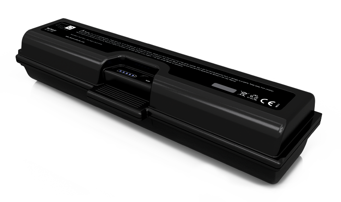
| DECAQ Battery | Li-Ion Battery 90 Wh Capacity Systems come standard with one removable battery |
| BMUX | Standard Battery Cartridge. All DECAQ systems come populated with the BMUX Battery Cartridge and one removeable battery |
| BMUXS | Battery Cartridge for additional batteries. Compatible with DECAQ-04, DECAQ-06. Populate your system with up to 3 batteries |
Battery and cartridge combinations
| SYSTEM | SYSTEM WITHOUT BATTERIES | BATTERY CAPACITY BMUX BATTERY CARTRIDGE STANDARD - 1 REMOVEABLE BATTERY | BATTERY CAPACITY BMUX BATTERY CARTRIDGE FOR ADDITIONAL BATTERIES |
|---|---|---|---|
| DECAQ-02 | 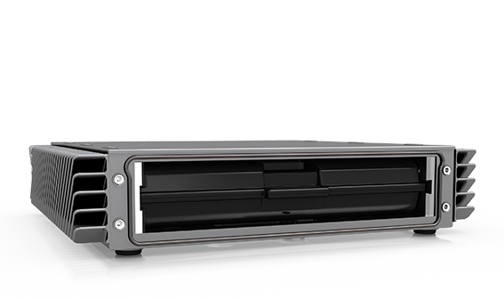 |
N/A | |
| DECAQ-03 | 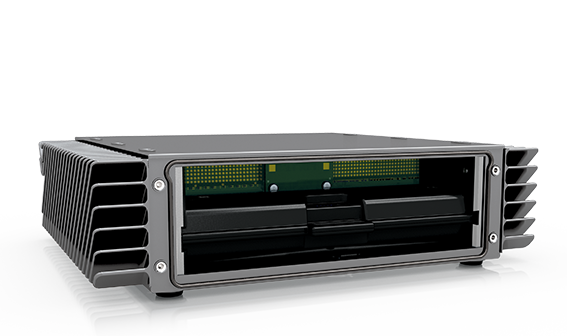 |
N/A | |
| DECAQ-04 | 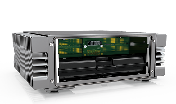 |
 Max
2 removeable batteries Max
2 removeable batteries |
|
| DECAQ-06 | 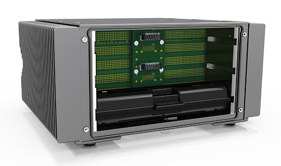 |
 Max
3 removeable batteries Max
3 removeable batteries |
The DECAQ Mainframes have been designed to be able to swap between different batteries.
Removal of a battery inside a Mainframe whilst powered down
Unscrew the hex key from the bottom cover of the DECAQ Mainframe
Use the hex key to unscrew the rear cover plate of the DECAQ Mainframe
Pull out the battery using the tab on its plastic housing
Return the rear cover plate to the DECAQ Mainframe
Return the hex key to the bottom cover of the DECAQ Mainframe
Insertion of a battery into a Mainframe whilst powered down
Charging the battery
There are two ways to charge the DECAQ battery:
Fast Charge
Fast charge can only be performed if the DECAQ is switched off. Charging times vary according to the chassis size – a 2-slot DECAQ with only one battery takes 2 hours to charge (the fastest charging time), whereas the 6- slot DECAQ with up to three batteries takes 5 hours to charge (the slowest charging time).
Fast charging will start automatically when external power is first connected to the DECAQ or when the DECAQ is switched off and the battery is not yet fully charged.
Fast charge uses approximately 90 W of electrical input power. If the input power supply is not capable of providing the power, the system might reset. This method also introduces additional heat into the system. It is therefore highly recommended that it be performed in an area with a free flow of cool air.
Dynamic Charge
This setting charges the battery as fast as possible while the DECAQ is switched on. With Dynamic Charge, all available power (up to 40 W) not being used by the system is diverted to the battery.
Input Currents and System Temperature
Dynamic Charge requires the total input current to be less than the set current limit before it will start charging. Once the system’s input current is less than the system current limit, charging will commence. Thereafter, the battery charge current will increase until maximum charge current is reached, or the input current rises to above the system current limit.
If the total input current rises above the system current limit during charging, the charge current will be reduced until the input current is below the system current limit or until zero charge current has been reached. Once zero charge current has been reached, the charge current will only increase once input current to the system falls below the system current limit.
Dynamic Charge Cycles and Termination
Dynamic Charge will start a charge cycle if the battery is not 100% full.
Dynamic Charge will terminate when:
The battery is fully charged (the battery is fully charged).
The main input power has been lost and the system goes into backup mode.
A fault is detected in the battery.
Dynamic Charge Deactivation
Once the setting has been changed to Dynamic Charge, the system will use it as the default setting. The setting can then be deactivated via the Web Server and will stay deactivated until the User activates the setting again.
Fast Charge does not affect Dynamic Charge (which is only applicable once the system is operational (DECAQ switched on)).
Only one of these two charge algorithms can be active at any given time.
The battery has to be charged for the DECAQ’s uninterruptible power supply (UPS) to supply the system with backup power. You can use any of the two settings to recharge a discharged battery. Fast charge is managed automatically when the system is switched off. Dynamic charge can be selected on the Web Interface.
The most efficient way of maintaining the battery is to use the new ‘Dynamic Charge’ setting. Dynamic Charge will ensure the system automatically keeps the battery in a fully charged state.
Alternatively, ‘Fast Charge’ can also be used to fully recharge a battery that has been depleted.
| Please note |
|---|
| If the external power source is removed while Dynamic Charge is in progress, the DECAQ will stop charging and switch to backup mode and run from the battery. If the external power source is removed while Fast Charge is in progress, the DECAQ will stop charging and switch off. Due to the properties of Li-Ion rechargeable batteries, recharging can only be initiated when the battery is between 0 °C and 45 °C. Once the temperature exceeds 50 °C while charging, charging is suspended and the Battery LED will flash red. Charging will resume once the battery temperature drops below 45 °C. Charging will also be suspended if the battery temperature drops below 0 °C, and will resume once the battery temperature rises to above 2 °C. |
| The Battery LED will flash red when the battery pack has gone above 50 °C or below 0 °C while being charged. In both cases, the system will cease to charge the battery: < 0 °C. While the battery pack is being charged, the battery pack will suspend charging once the temperature is < 0 °C. Once this happens, the Battery LED will flash red. Charging will resume once the battery temperature rises to above 2 °C. |
| 0 °C - 45 °C This is the valid battery pack temperature range for starting a charge cycle. The Battery LED will flash blue while charging. > 50 °C While the battery pack is being charged, the temperature at which the battery pack will suspend charging is > 50 °C. Once this happens, the Battery Led will flash red. This is for safety reasons as it is better for the battery pack to be charged at lower levels. Charging will resume once the battery temperature drops below 45 °C. |
Recommended battery replacement interval (Li-Ion batteries)
To ensure Li-Ion batteries are functioning at full capacity, it is recommended they be replaced every three years.
Mecalc does not repair batteries that are out of warranty. Please ensure that spent batteries are disposed of responsibly by recycling them at local recycling facilities in accordance with relevant local regulations. Proper disposal helps protect the environment and reduces hazardous waste. Contact your local waste management services for guidance on battery recycling locations and procedures.
Battery Care
For optimum battery care, charge or discharge DECAQ batteries to approximately 50% capacity at least once every six months. This ensures batteries maintain their maximum energy capacity. Store the battery at temperatures between 5 °C and 20 °C (41 °F and 68 °F) and 50% capacity.
Before switching on the DECAQ, make sure it is being powered with an external power source or contains a charged battery.

Switch on the DECAQ via the User Interface by applying the following steps:
See Navigating the DECAQ’s User Interface Display for more information about the User Interface display.

Switch off the DECAQ via the User Interface by applying the following steps:
| Please note |
|---|
| Take care not to switch off your DECAQ while it is running a test. The procedure above will shut down the system irrespective of whether a test is being run or not. Please ensure the test sequence has concluded before switching off the system, since valuable data may be lost if the test is still running. |
The DECAQ can be connected to a Notebook / PC / network / smart device through Ethernet and/or Wi-Fi.
A built-in 2 MIMO streams IEEE 802.11b/g/n Wi-Fi network interface is available on the DECAQ. The Wi-Fi network interface can be used where truly mobile operation of the DECAQ is required.
The default configuration for the DECAQ Wi-Fi interface is:
Connect to the DECAQ with your compatible Wi-Fi device using the SSID mentioned above. To test connectivity, use the default IP address as the URL in a web browser, for example, http://192.168.2.204.
The default mDNS name may also be used in compatible web browsers, for example, http://Quantus_1234S5678.local.
The browser should then display the DECAQ’s “System Overview” page. The DECAQ’s start-up Wi-Fi interface configuration parameters can be edited in the Web Server’s network setting configuration pages.
Effective Wi-Fi data streaming rates of up to 2.7 MB/s can be achieved with your DECAQ. Please note that your DECAQ Wi-Fi connection performance is highly dependent on its connection settings, as well as environmental factors including (but not limited to) distance, interference and shared bandwidth.
| Please note |
|---|
| When configuring the Wi-Fi interface, the settings for “Country”, “IP address” and “Subnet mask” might be different depending on the country in which you are setting up the device. |
A Gigabit Ethernet connection (1000 BASE-T) is available on the DECAQ’s front panel that can accept compatible Ethernet cables. When using Ethernet on the DECAQ use only a CAT5e UTP cable. This will ensure the correct screening of signals throughout the length of the cable.
The default configuration for the DECAQ Ethernet interface is:
To use the Ethernet interface, simply plug in an Ethernet cable. The DECAQ will automatically detect the Ethernet cable and initialize it as the primary network interface. Use a Gigabit Ethernet enabled link partner (network device or PC) for best performance.
To test connectivity to the DECAQ, use a web browser that supports mDNS and enter the URL “http://Quantus_1234S5678.local” (replace “1234S5678” with the Serial Number of the DECAQ).
The browser should then display the DECAQ “System Overview” page. The DECAQ’s start-up Ethernet interface configuration parameters can be edited in the Web Server’s network setting configuration pages.
Once booted, the User Interface can also be used to display the system’s IP address. The DECAQ Web Server can then be used (with the IP address as the URL) to make modifications to the network set-up.
Ethernet Connection Range and Cables
Gigabit Ethernet over copper (1000BASE-T) connections allow for cable lengths of up to 100 m. If a longer connection distance is required, active repeaters need to be used at each 100 m interval.
DECAQ system information is available on the Web Server. This includes all boards that make up the specific system, their serial numbers and firmware. The following DECAQ parameters are shown and can be configured via the Web Server (please note the user interface of the web server depends on the firmware version and some settings may not be applicable):

Button and the OK Button).
To control the User Interface, press the Scroll Button to scroll down the menu options shown on the display. Use the OK Button to select an item from the menu to execute its related command. As a safety feature the display might show ‘SURE?’, asking the user to confirm the command before the system will execute it.
Options on the User Interface will continue to loop if the user continues to press the Scroll Button.
The OLED display is automatically dimmed when no screen or User input activity has been detected.
| Please note |
|---|
| Do not switch off or reset the DECAQ while it is busy booting or while a firmware upgrade is taking place, as this could permanently damage the system. Wait for the User Interface to display ‘IDLE’, ‘LIVE’, ‘REC’ or ‘FAIL’ before executing additional commands. |
The following menu options will be available on the User Interface display once the DECAQ has been switched on (to scroll through these options, press the Scroll Button until the option appears on the display):
 |
IDLE Default text displayed on the DECAQ User Interface |
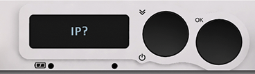 |
IP? Displays the mDNS name, IP address of LAN and Wi-Fi |
 |
RESET? Reset the DECAQ |
 |
OFF? Power down the DECAQ |
 |
TEMP? Power Supply temperature |
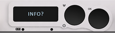 |
INFO? Information and firmware revisions of the DECAQ |
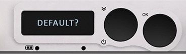 |
DEFAULT? Changes boot parameters of the DECAQ back to the system’s default settings |
The menu options on the User Interface cycle in a repetitive loop – press the Scroll Button to scroll from INFO? to IP? and so on.

To display the IP address on the User Interface display:
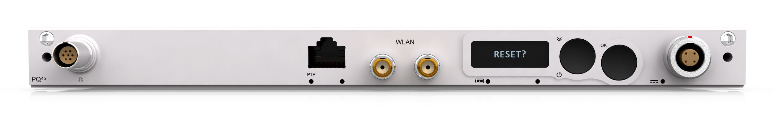
To reset the DECAQ:
| Please note |
|---|
| Resetting the system using this procedure overrides any operation currently being performed. The DECAQ will therefore be reset irrespective of whether a test is running or not, increasing the risk that valuable data may be lost. |


To let the display show the status of the chassis temperature:
The display will show OK and thereafter the temperature of the chassis, for example 40 °C.

This menu option shows information and firmware versions related to the DECAQ.
To view the information:
Examples of the information displayed include:
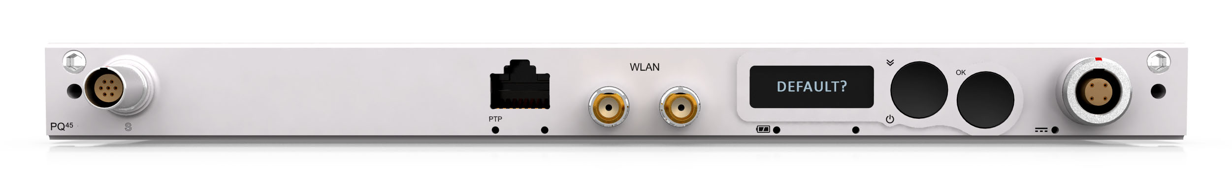
To restore the system to its default boot parameters:
The default boot settings of the DECAQ System board are:
| LAN IP address | DHCP assigned IP address (will default to an Automatic Private IP address such as 169.254.119.144 if no DHCP Server is discovered) |
| LAN DHCP Mode | DHCP client enabled |
| WLAN IP address (if present) | 192.168.2.204 |
| WLAN DHCP Mode | DHCP server enabled |
| LAN / WLAN Bridged Mode | Disabled |
| FTP password | password |
| mDNS name | Quantus_[Serial number printed on the bottom of the system] |
  |
SWITCHED OFF / CHARGING While the DECAQ is switched off (and power is available) or charging the internal battery, the User Interface display will either be blank - or display CHARGING. |
 |
HELLO To switch on the DECAQ from
this state, press and hold the Scroll
Button until
the LEDs flash and the User Interface displays
HELLO. |
For more about the User Interface Display and Menu Options while the DECAQ is switched on.
When the DECAQ is switched on it will begin to boot up with firmware stored in its internal Flash memory. There are three stages to booting up correctly:
During boot up the device will show the following messages on the User Interface:
 |
BUSY This message is displayed when the system board is booting after Power On (cold boot) |
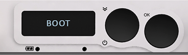 |
BOOT This message is displayed while the System board is booting |
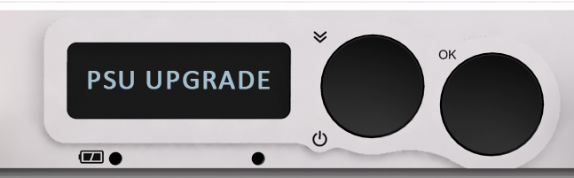 |
PSU UPGRADE This message is displayed during the Power Supply firmware upgrade. The status LEDs will also flash yellow to indicate the system is still active. This process can take several minutes to complete. The User must not switch off the system during the upgrade. Power Supply firmware upgrades typically take place after the DECAQ has been programmed with new firmware. |
|
FPGA UPGRADE This message is displayed during the FPGA firmware upgrade. The status LEDs will also flash yellow to indicate the system is still active. This process can take several minutes to complete. The User must not switch off the system during the upgrade. FPGA firmware upgrades typically take place after the DECAQ has been programmed with new firmware. |
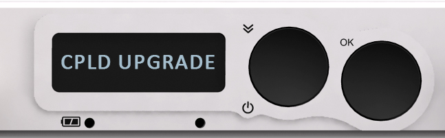 |
CPLD UPGRADE This message is displayed during the CPLD firmware upgrade. The status LEDs will also flash yellow to indicate the system is still active. This process can take several minutes to complete. The User must not switch off the system during the upgrade. CPLD firmware upgrades typically take place after the DECAQ has been programmed with new firmware. |
 |
WAIT This message is displayed when the system board starts to initialize the Signal Conditioning cards. |
 |
xx% This is the progress indicator displayed during the Signal Conditioning and QModule boot-up. |
|
IDLE This message will be displayed once the boot-up is complete |
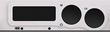
The DECAQ User Interface’s LEDs indicate when the system is active and provides information about different DECAQ Ethernet, Battery and Power statuses.
Below find a brief explanation of each LED action and what it represents:
Ethernet Connector (PTP) LED
The Ethernet connector LED labeled “PTP” is used to indicate the status of the Ethernet link as well as the PTP synchronization status of the system. The following table lists the different states of the LED.
| Solid / Flash / Off | Colour | Description |
|---|---|---|
| Off | N/A | Ethernet is not connected (connection faulty or cable disconnected). |
| Solid | Blue | Ethernet is connected. System is not PTP Slave, not PTP Master and does not have a synchronization fault. |
| Solid | Green | Ethernet is connected and system is PTP Slave. |
| Solid | Red | Ethernet is connected but system has a synchronization fault. |
| Flashing (1 Hz) | Green | Ethernet is connected and system is PTP Master but not PTP Grandmaster. |
| Flashing (0.5 Hz) | Green | Ethernet is connected. System is PTP Master and PTP Grandmaster. |
Battery Status LED
| Solid / Flash / Off | Colour | Description |
|---|---|---|
| Off | N/A | Battery power is not available / not present. |
| Solid | Blue | Battery power is available but isn’t being used to power the system. |
| Solid | Green | Battery is being used to power the system. |
| Solid | Yellow | Battery capacity is less than 25%. |
| Flashing (1 Hz) | Blue | Battery is busy charging. |
| Flashing (1 Hz) | Yellow | Battery capacity is less than 10%. |
| Flashing (1 Hz) | Red | Charging pending. Battery pack temperature is out of range and charge is suspended until battery pack temperature is valid for charging. |
Application LED 1
The LED underneath the User Interface Display on the right is a “soft” LED. The meaning of the LED light changes depending on the application. It could be used to indicate standby / sleep / heartbeat / system activity – it is undefined for now.
DC Power LEMO LED
| Solid / Flash / Off | Colour | Description |
|---|---|---|
| Off | N/A | External power not available. |
| Solid | Blue | External power is available but not being used to power the system. |
| Solid | Green | External power is being used to power the system. |
| Solid | Red | The power input voltage is above or below the allowed voltage range; or the polarity of the input supply is incorrect. |
The DECAQ’s Signal Conditioning QModules are housed in the system’s Signal Conditioning boards, each board providing signal processing and mechanical infrastructure for up to 4 QModules.
These boards provide:
The DECAQ system contains multiple slots that support a variety of interchangeable Signal Conditioning channels (QModules), which can be purchased separately and then added and/or swapped as the need arises. QModules are packaged in a robust aluminium casing so as to optimize size and thermal performance, as well as to provide electronic protection.
All QModules include the following features:
Available Modules and a summary of their features are presented in the following section. More information regarding specific Modules (eg. Specification Sheets) is available in separate documents which can be requested from your supplier.
Description
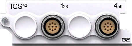
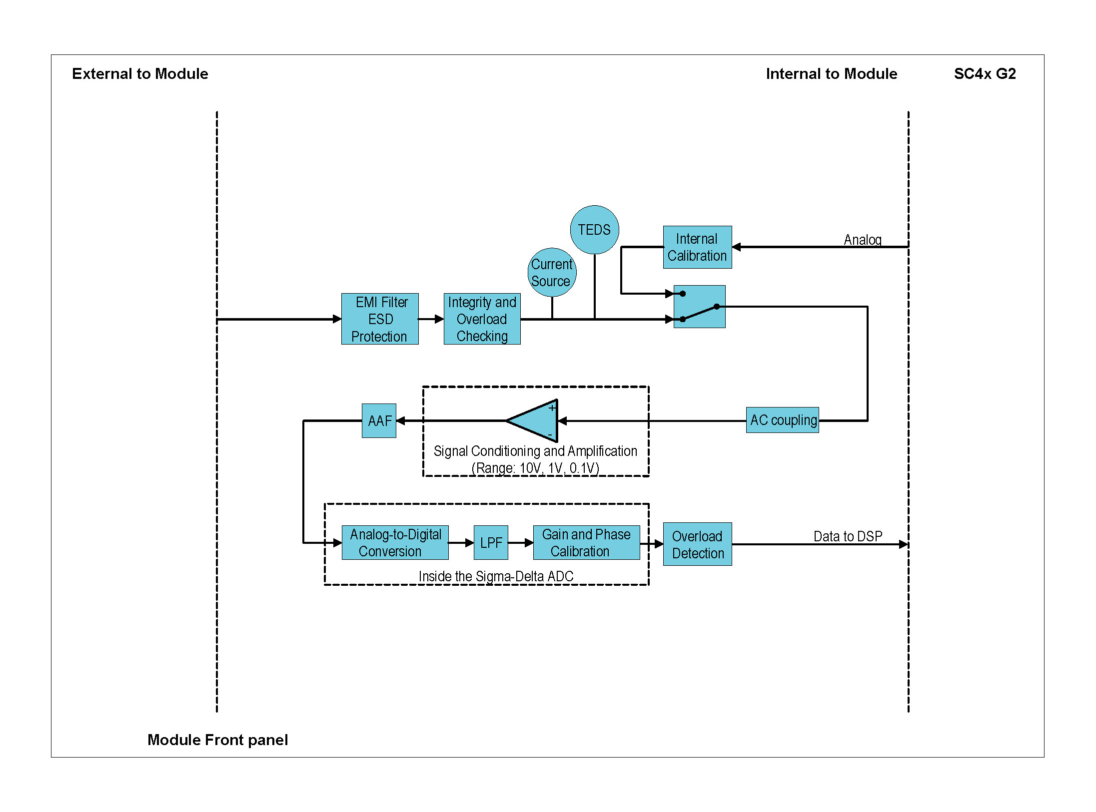
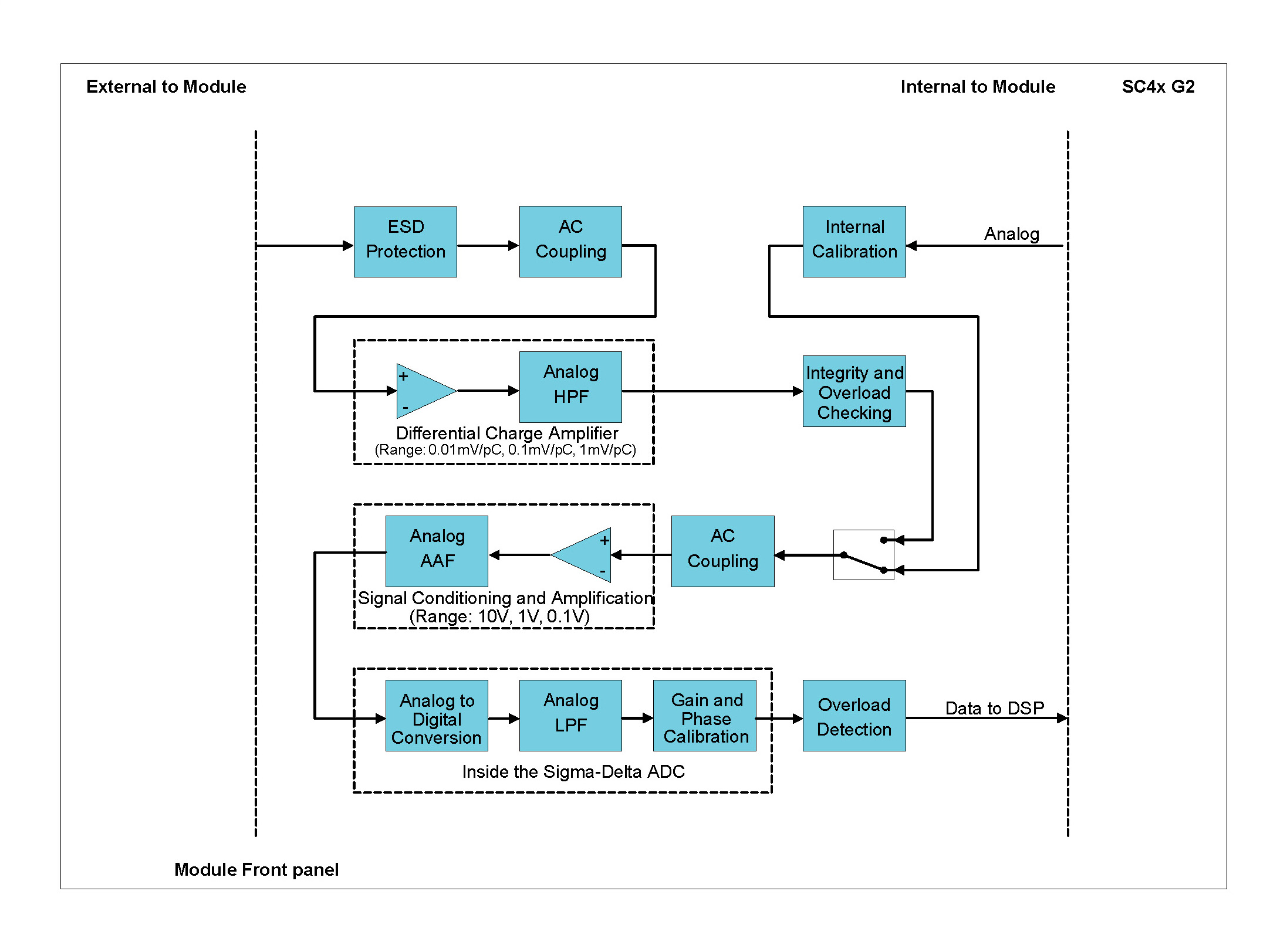
The ICS42 Module can be used with ICP® based accelerometers, force and pressure sensors as well as to measure analog voltages. All 6 channels operate independently of each other, each with their own setting of mode, gain and coupling. The Module can be used:
| Front Panel | Connector Information and Pin Definitions |
|---|---|
 |
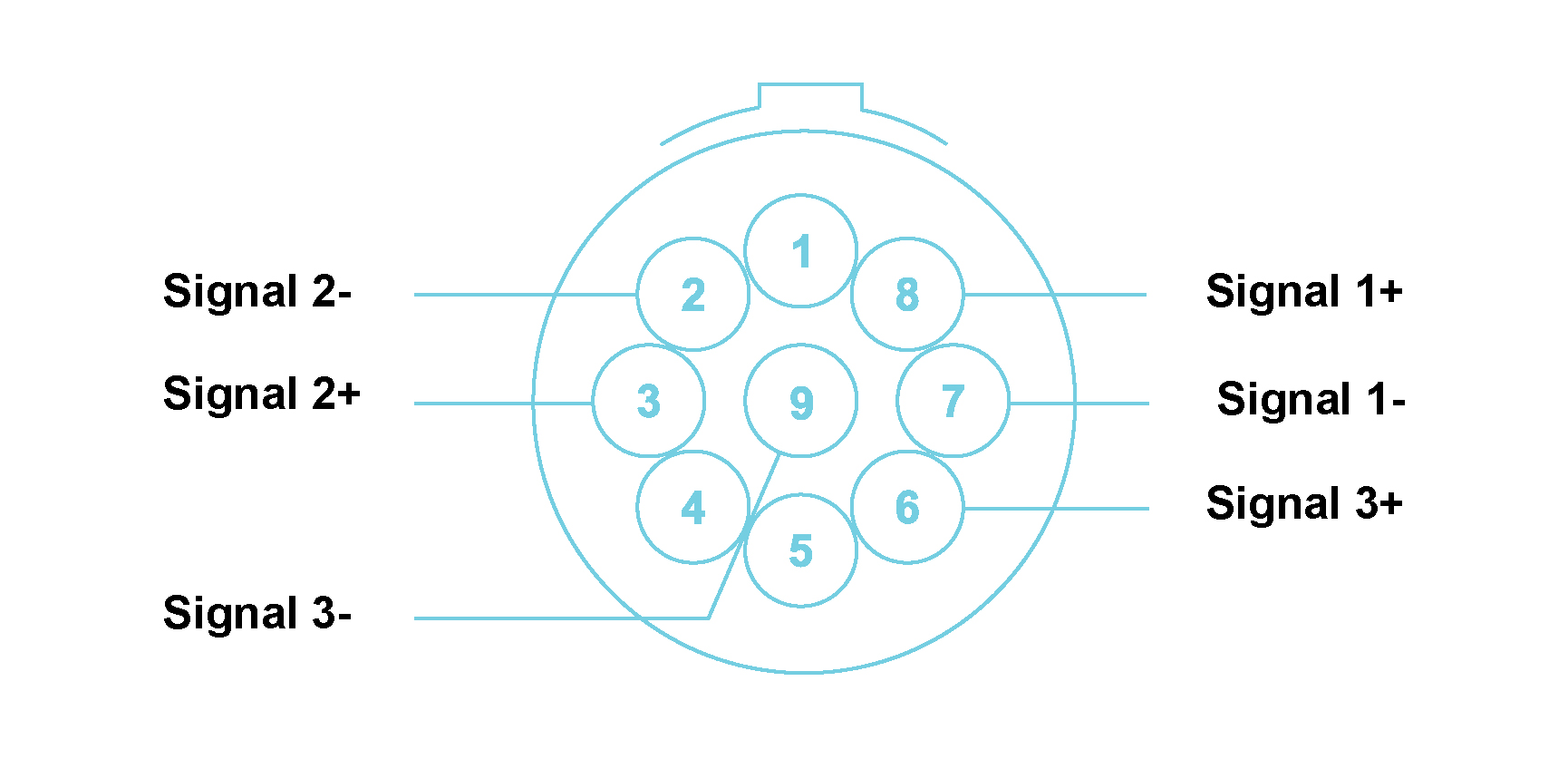 |
ICS42 with LEMO® 9-way EHG.0B connectors Module Pin Definition (when looking into the front panel’s connector or at the rear of the cable’s connector)
Features
Please note:The features and specifications may vary based on the software package utilized with the DECAQ
ICS42 Specifications
| Interface | ICP® | ICP® sensors | |||
| ALI | For analog source voltages | ||||
| Input Coupling | ICP® | AC | |||
| ALI | DC or AC | ||||
| AC Coupling Frequency Response | ICP®/ALI | Attenuation | Min | Max | Unit |
| -3 dB | − | 0.16 | Hz | ||
| Other Sampling Rates | Available through digital LP filters and decimation | ||||
| Optional Programmable Digital IIR Filter | Band pass/stop: 6 dB/octave | ||||
| High/Low pass: 12 dB/octave | |||||
| Optional First Order High-Pass Filter | -3 dB @ 1 Hz | ||||
| Protection | ICP®/ALI | 2 kV ESD | |||
| ICP® | Short circuit between sensor case and ground | ||||
| Galvanic Isolation | 50 V | ||||
| Bandwidth | DC to 44.3 kHz | ||||
| Maximum Sampling Rate (fs) per channel | 102.4 kSa/s | ||||
| A/D Conversion | 24-bit | ||||
| Data Transfer | 24-bit | ||||
| Input Voltage Ranges (Peak) | ±100 mV; ±1 V; ±10 V | ||||
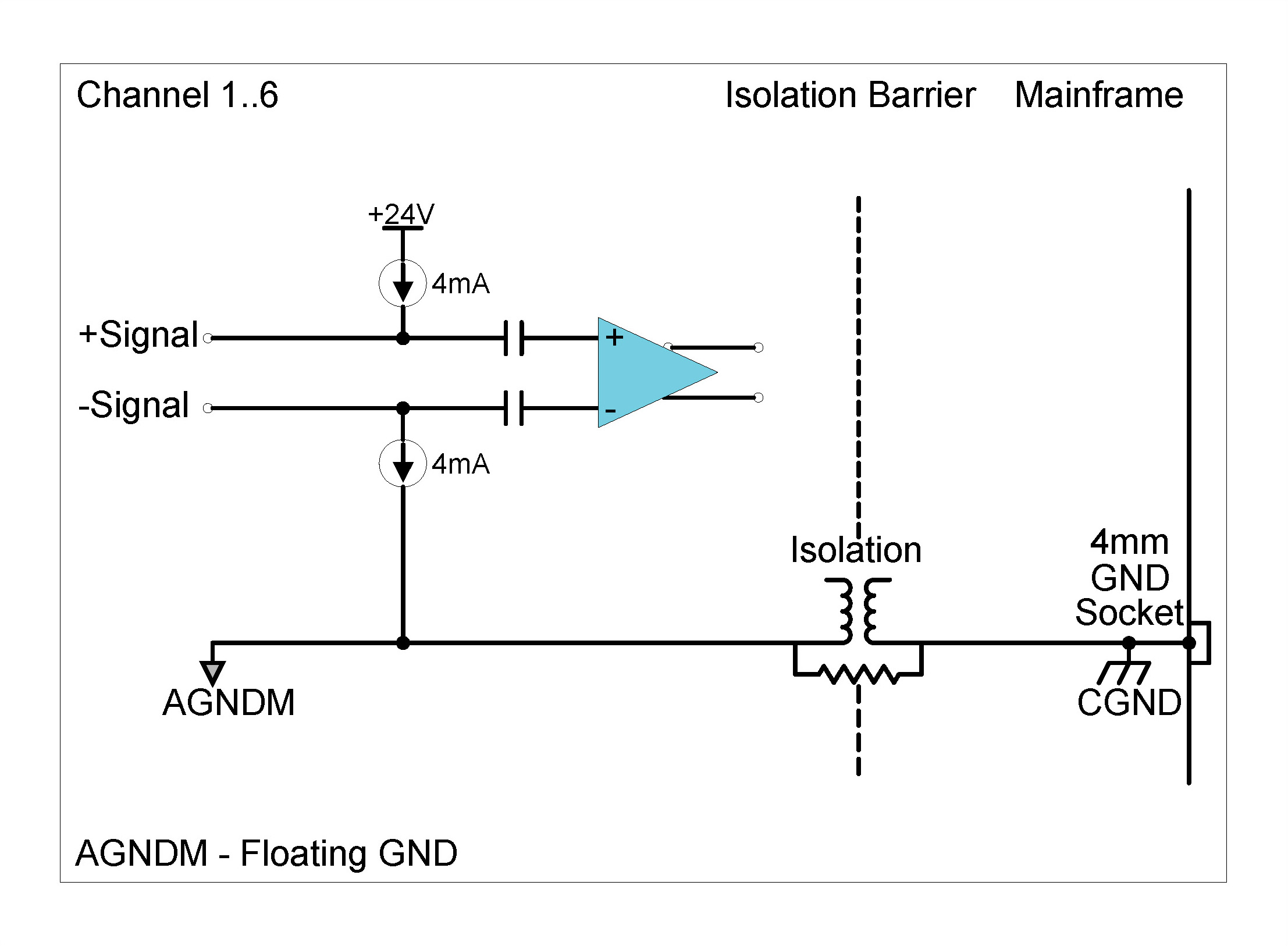
| ICP® mode | 4 mA constant current at 24 V excitation | ||||
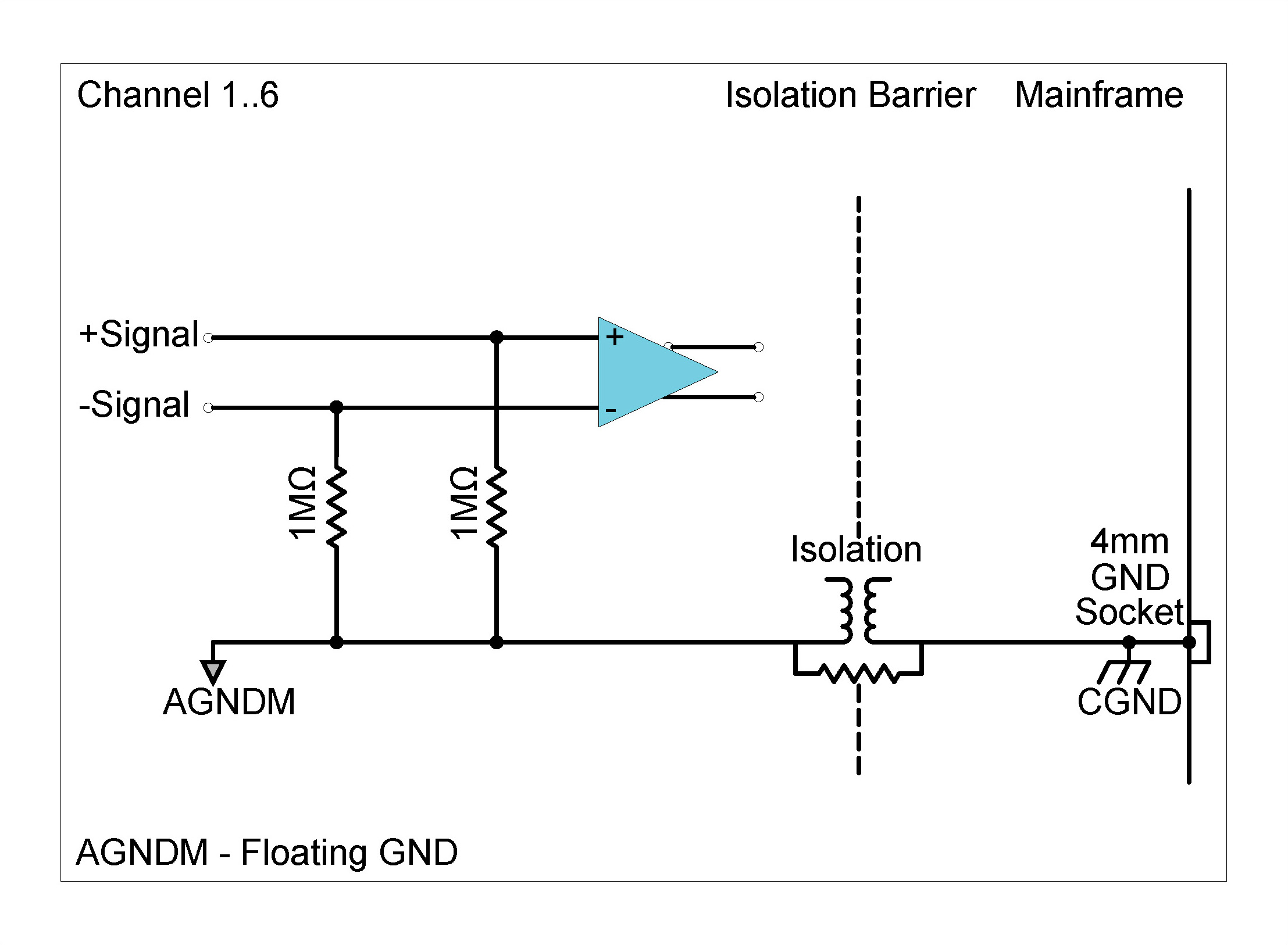
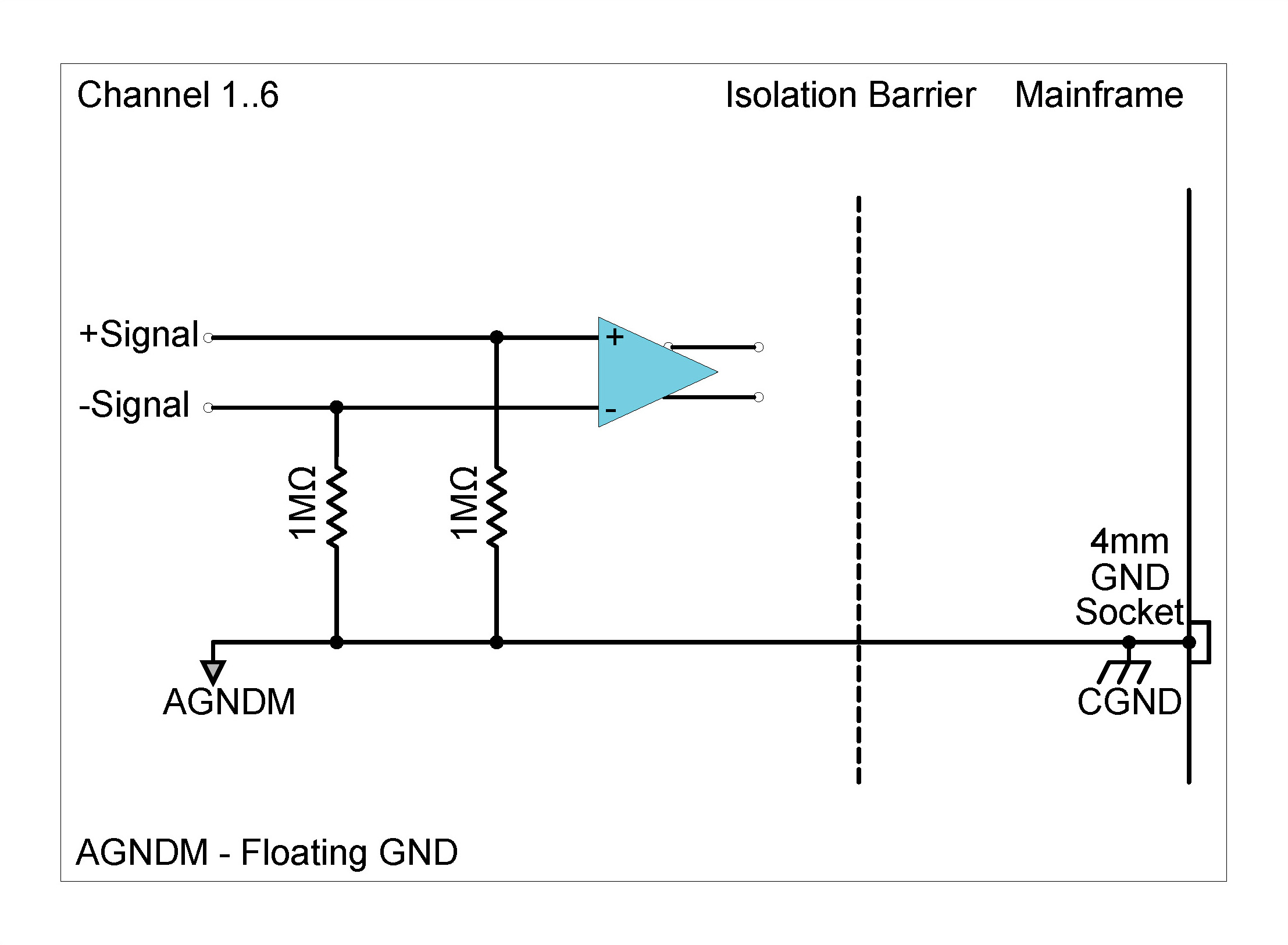
| Input Biasing Settings | Differential Float (Balanced Float) | Both the positive and negative signal inputs are connected through 1 MΩ to floating ground | |||
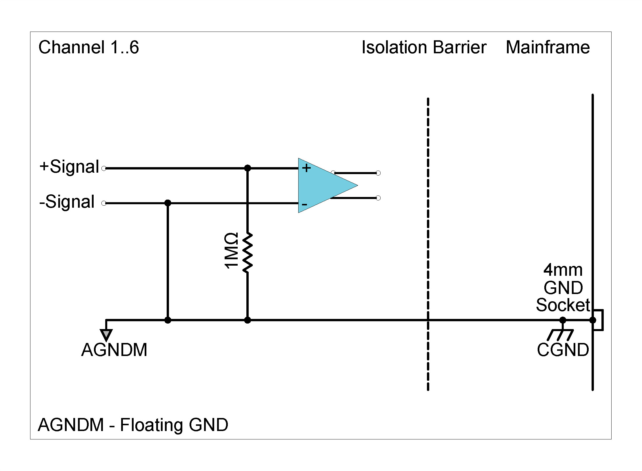
| Single-Ended Float (Unbalanced Float) | Positive signal input connected through 1 MΩ to floating ground; Negative signal input connected to floating ground | ||||
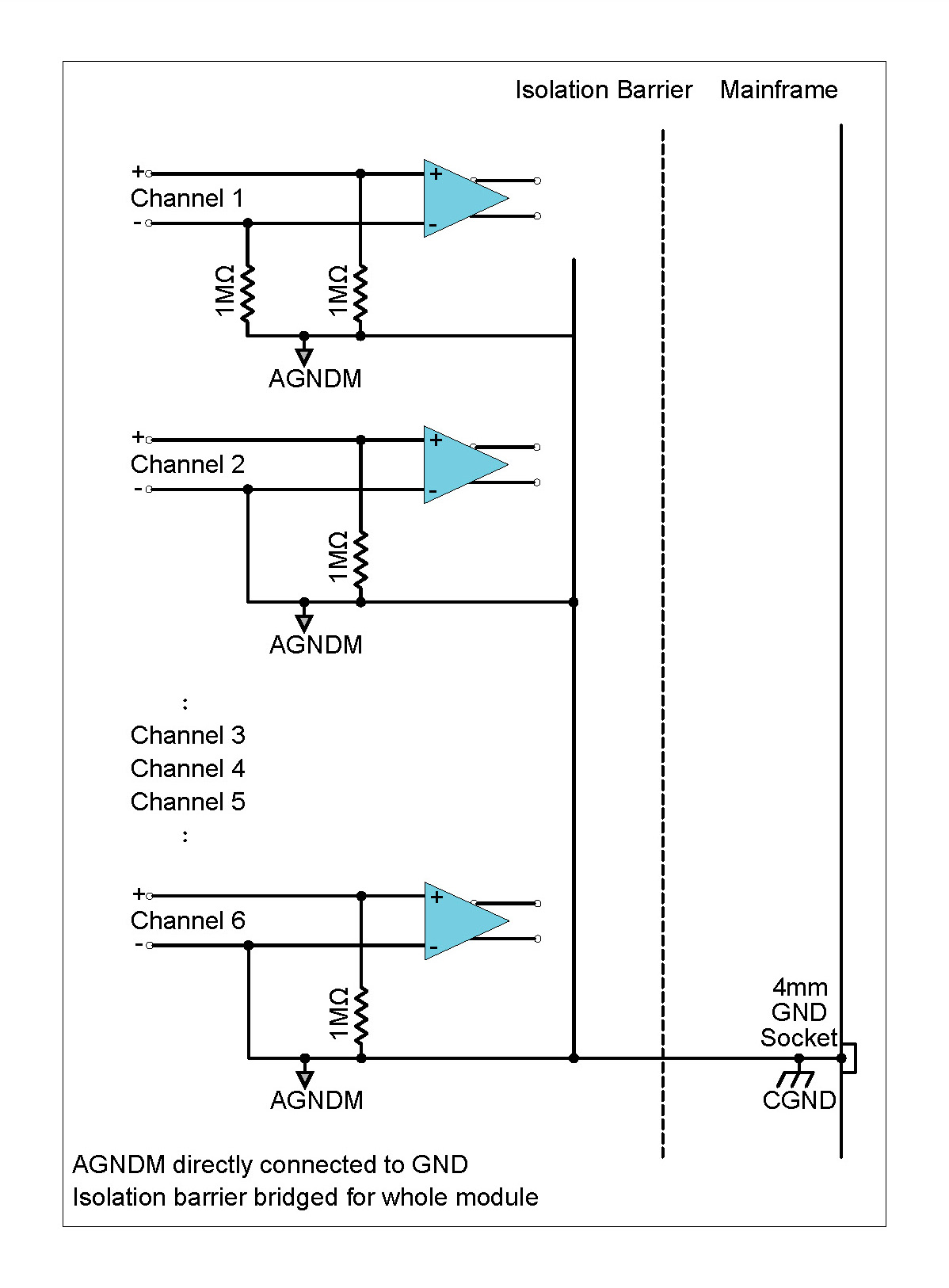
| Single-Ended GND (Unbalanced GND) | Positive signal input connected through 1 MΩ to ground; Negative signal input connected to ground | ||||
| Input Impedance | Differential | 2 MΩ ‖ 80 pF | |||
| Single-Ended | 1 MΩ ‖ 100 pF | ||||
|
Digital Low-Pass Filter Filter scales with sampling rate |
Passband | fs x 0.433 Hz | |||
| Stopband | fs x 0.499 Hz | ||||
| Passband ripple | ±0.005 dB | ||||
| Stopband attenuation | 105 dB | ||||
|
Phase Accuracy Channels in similar range |
Typical1 | <0.2° at 10 kHz> | |||
ICS42 Specifications
[1] Measured in 10 V range at 102.4 kSa/s
ICS42 Specifications continue
| DC Voltage Accuracy | Input Range (Peak) | Reading + % Range | ||
| ±100 mV | 0.200 % + 0.200 % | |||
| ±1 V | 0.068 % + 0.020 % | |||
| ±10 V | 0.113 % + 0.015 % | |||
|
Noise Input terminated by 50 Ω resistor |
Input Range (Peak) | Guaranteed | Typical | |
| 10 Hz to 22 kHz | ±100 mV | < 2.6 µVrms | < 2.2 µVrms | |
| 10 Hz to 44.3 kHz | < 4 µVrms | < 3 µVrms | ||
| 10 Hz to 22 kHz | ±1 V | < 9 µVrms | < 6 µVrms | |
| 10 Hz to 44.3 kHz | < 14 µVrms | < 10 µVrms | ||
| 10 Hz to 22 kHz | ±10 V | < 45 µVrms | < 40 µVrms | |
| 10 Hz to 44.3 kHz | < 113 µVrms | < 84 µVrms | ||
|
Dynamic Range2 Input terminated by 50 Ω resistor |
Input Range (Peak) | Typical | ||
| ±100 mV | > 120 dB | |||
| ±1 V | > 130 dB | |||
| ±10 V | > 130 dB | |||
|
Signal to Noise Ratio Input terminated by 50 Ω resistor |
Input Range (Peak) | Typical | ||
| ±10 V | > 104 dB; 22 kHz bandwidth | |||
|
Amplitude Flatness Relative to 1 kHz Measured up to 0.39 x fs |
Sampling Rate (fs) | Input Range (Peak) | Attenuation (Input signal level 100 % of full range) | |
| 51.2 kSa/s | ±100 mV | − 0.06 dB | ||
| 102.4 kSa/s | − 0.10 dB | |||
| 51.2 kSa/s | ±1 V | − 0.04 dB | ||
| 102.4 kSa/s | − 0.05 dB | |||
| 51.2 kSa/s | ±10 V | − 0.03 dB | ||
| 102.4 kSa/s | − 0.04 dB | |||
| Crosstalk | Input Range (Peak) | Guaranteed | Typical | |
| ±100 mV | 113 dB | 118 dB | ||
| ±1 V | 110 dB | 115 dB | ||
| ±10 V | 102 dB | 107 dB | ||
ICS42 Specifications
2 Dynamic range calculated at sampling rate of 51.2 kSa/s,
with a 4096-point FFT.
Specification number: SP151000, Release 2.4. The Module settings and measurement conditions that were used during specification measurements are available on request.
Functionality per Channel
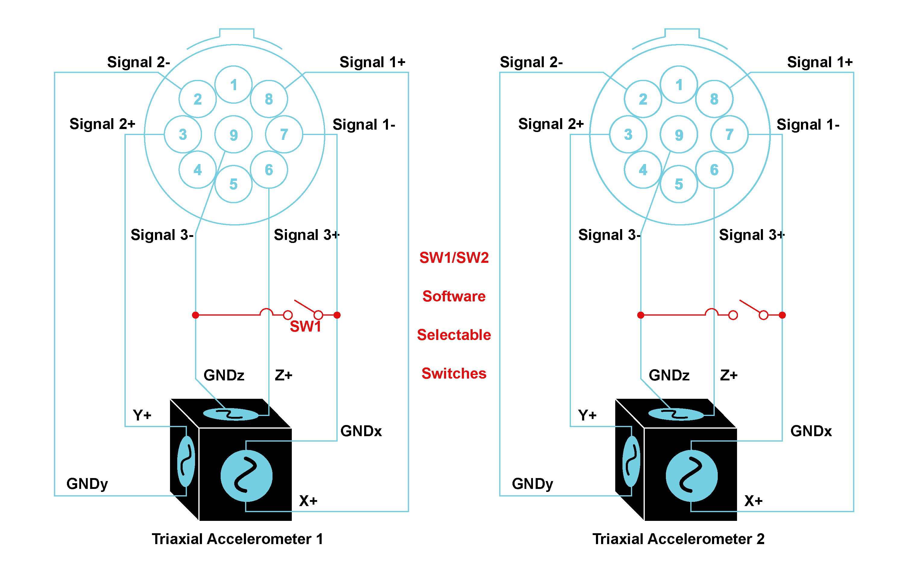
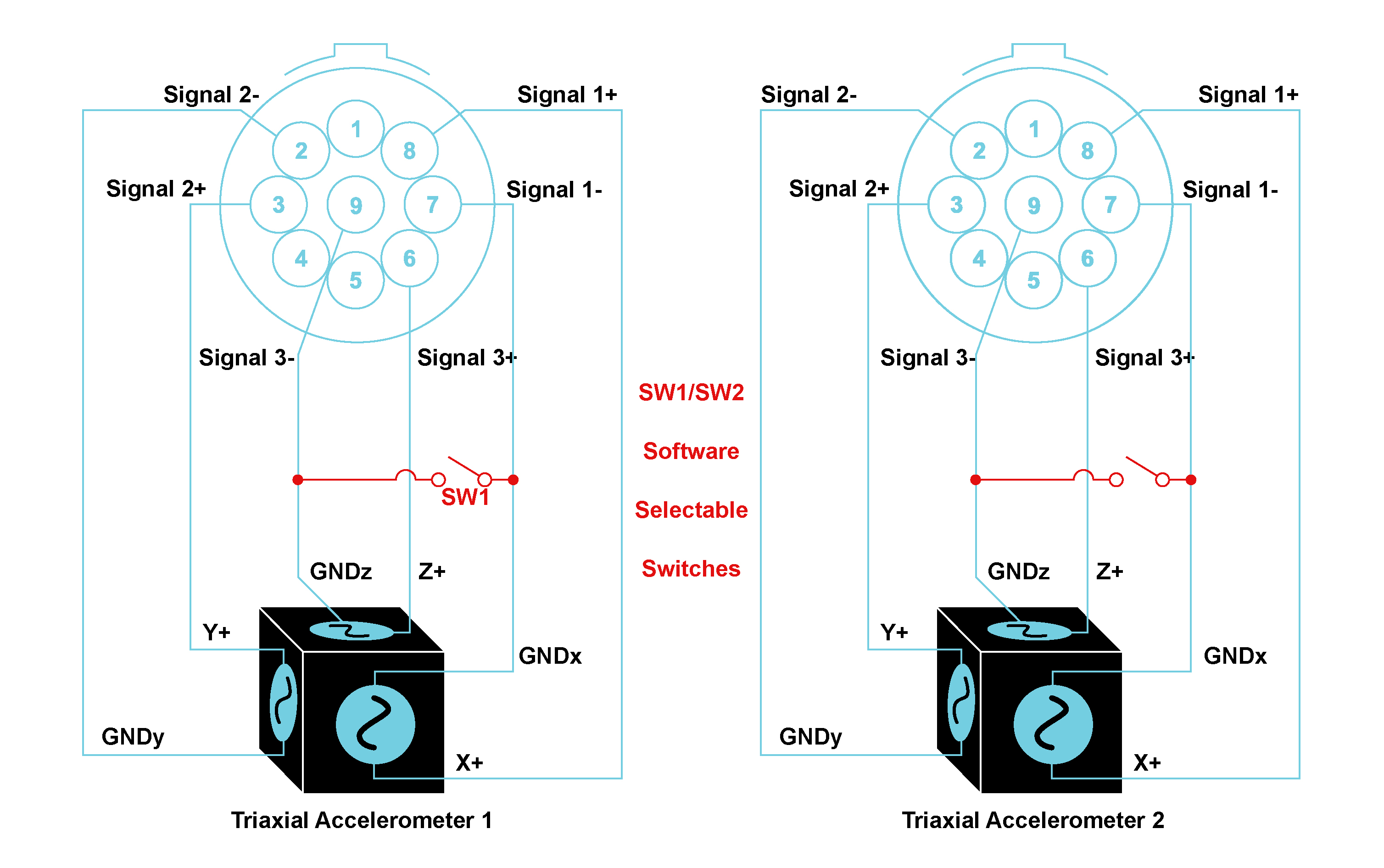
Accelerometer connections per Module
The ICS42 can accept inputs from single ICP® accelerometers as well as triaxial ICP® accelerometers. The connectors on the front panel are ideally designed to connect to two triaxial sensors per Module. The LEMO® 9-way EHG.0B connectors Module Pin Definition indicates where the signal connections of each X, Y and Z and the common return of the triaxial sensor can be connected.
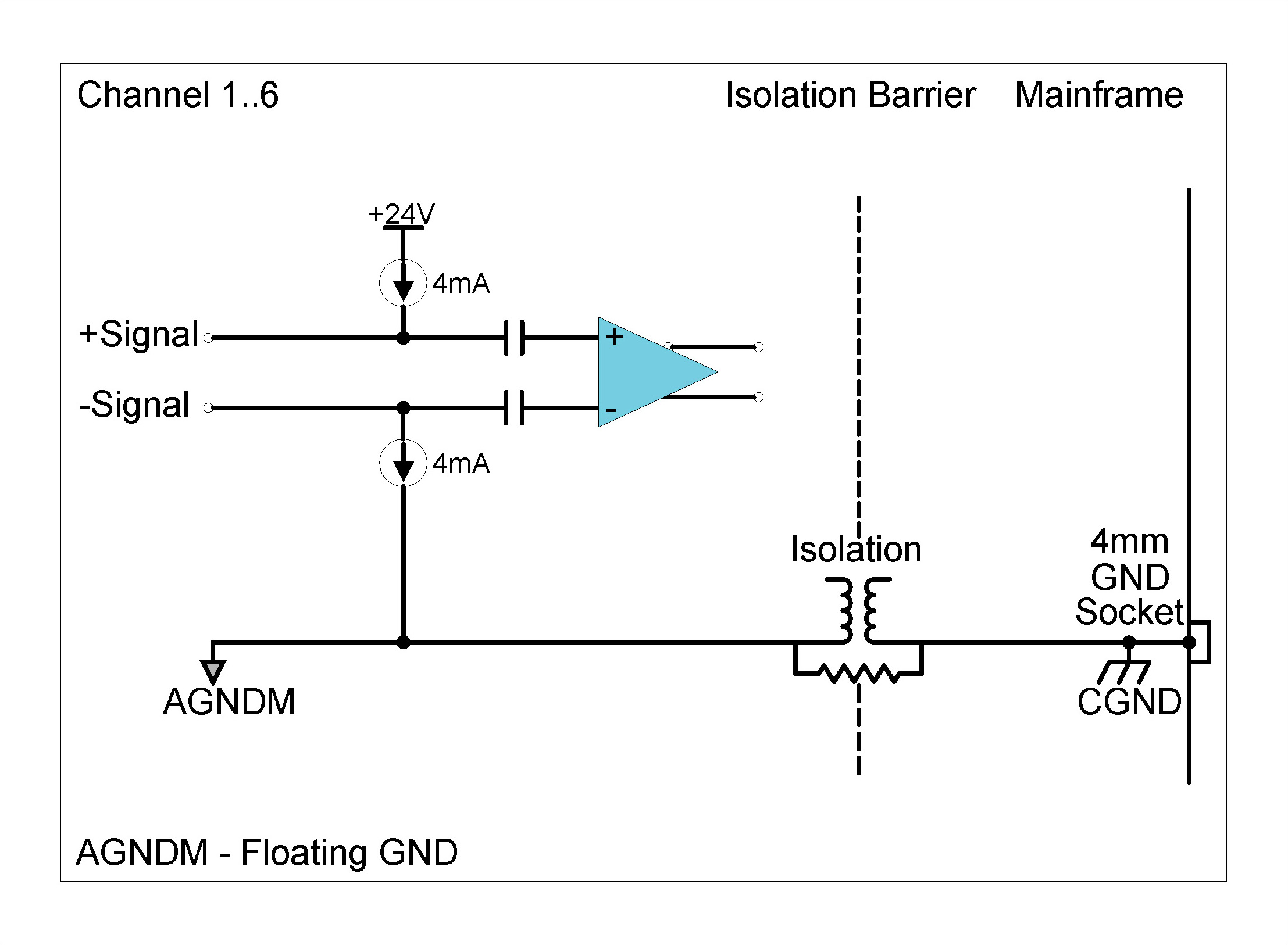
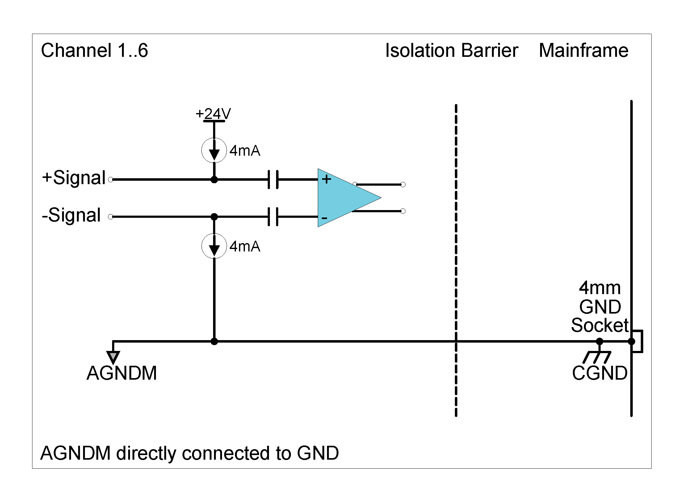
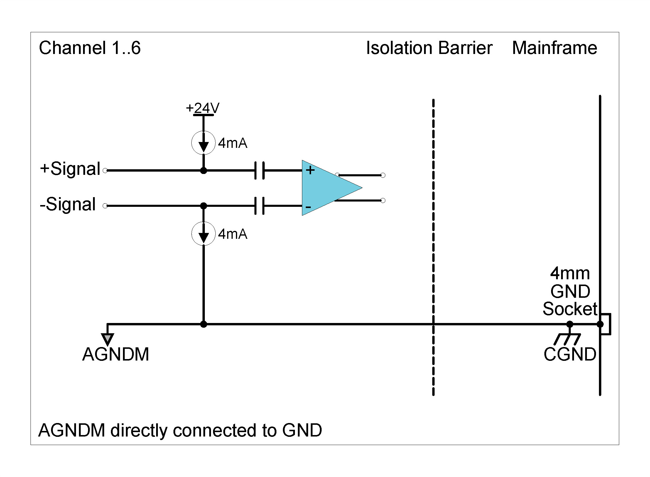
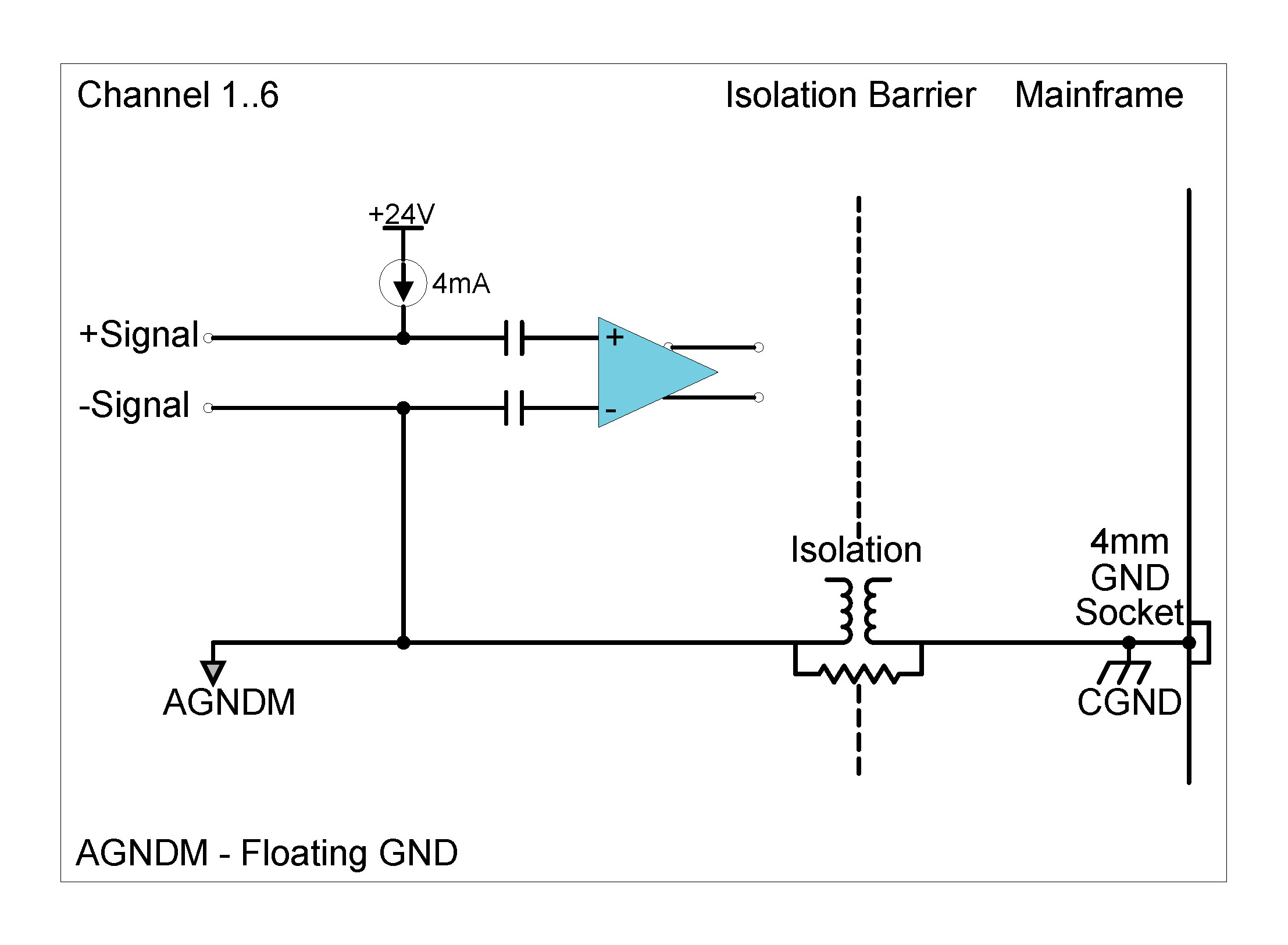
Grounding options
There are four ALI mode grounding options available on the ICS42:
Grounding Diagrams: ALI mode (Voltage Input mode)
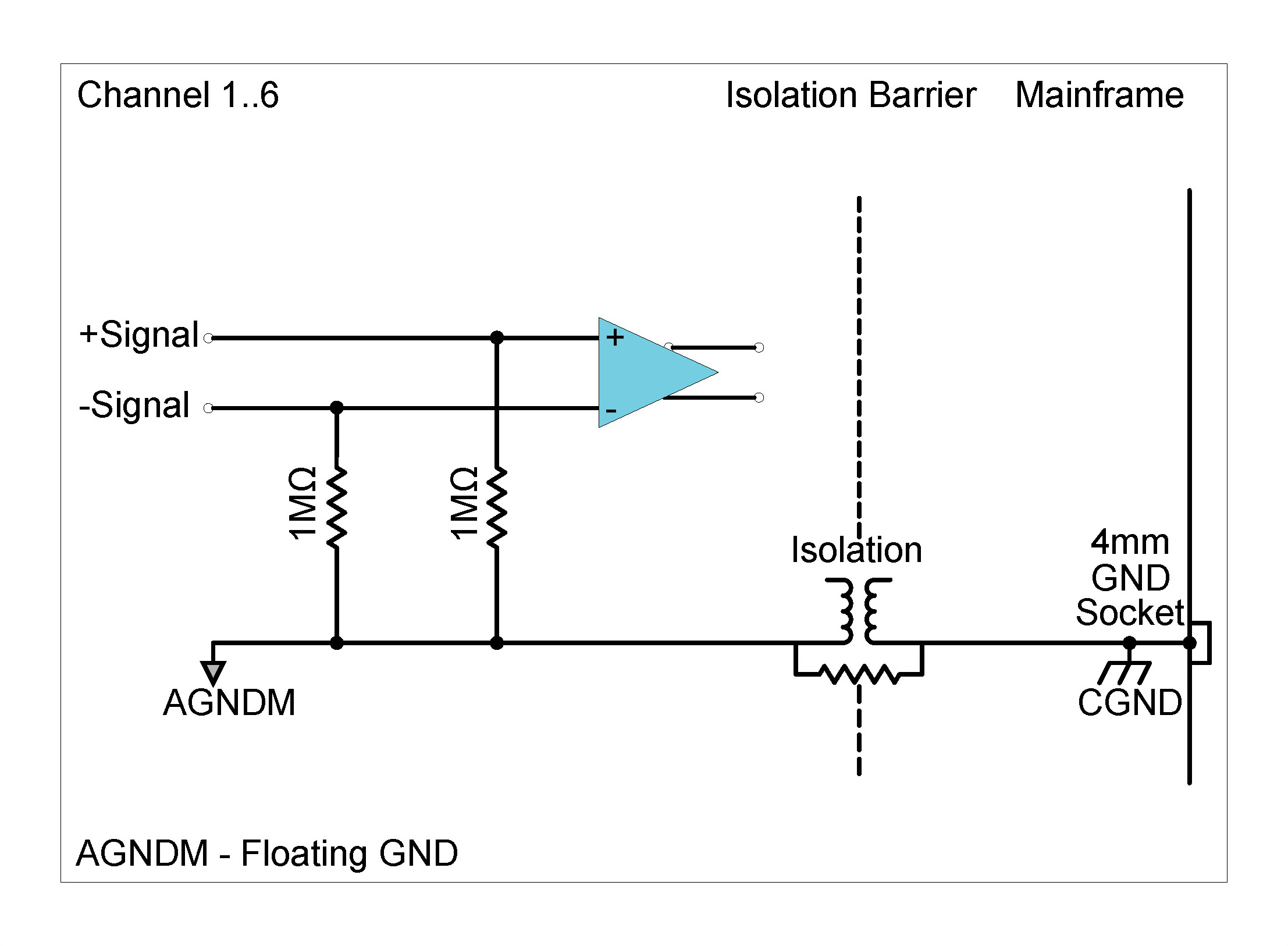


Although each channel in the ICS42 can be set individually as to its grounding type, enabling the ground option on any one channel will cause the isolation barrier of the module to be bridged (i.e. on all six channels AGNDM will be directly connected to CGND).

Excitation Diagrams: ICP® Mode
There are two biasing options when using ICP® input mode with 4 mA current excitation, either differential of single-ended. The Biasing settings are independent of the grounding options. The following table shows the different possible settings for the ICS42 Module in ICP® input mode:
| Excitation voltage | Biasing settings | Grounding options |
|---|---|---|
| 24 V (Asymmetrical) | Differential | Ground or Floating ground |
| 24 V (Asymmetrical) | Single-ended | Ground or Floating ground |
ICS42 Module Settings in ICP® input mode with 4 mA current excitation


Description
The CHS42X Module can be used with ICP® based accelerometers, force and pressure sensors, quartz or piezoelectric ceramic sensors or to measure analog voltages. The Module can be used:
| Front Panel | Connector Information and Pin Definitions |
|---|---|
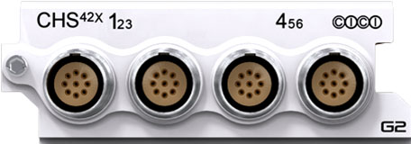 |
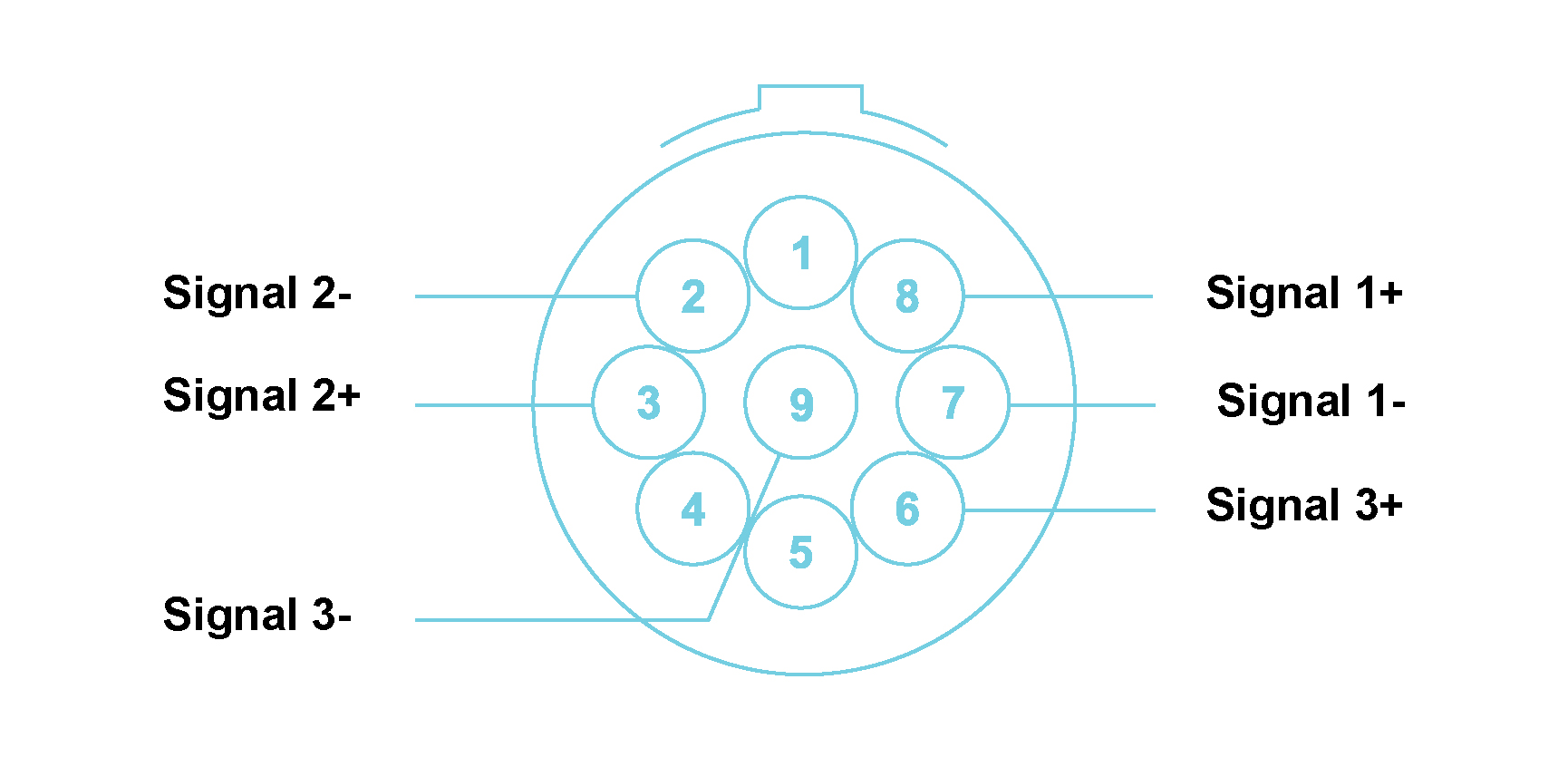 |
CHS42X with LEMO® 9-way EHG.0B connectors Module Pin Definition (when looking into the front panel’s connector or at the rear of the cable’s connector)
ESD WARNING The CHS42X Module inputs are sensitive to ESD damage. Always take care to discharge any additional static electricity that might have built up on a cable and connector before making contact with the CHS42X Module.
ICP® and Voltage Input Mode Features
Please note:The features and specifications may
vary based on the software package utilized with the
DECAQ
CHS42X ICP® and Voltage Input Mode Specifications
| Interface | ICP® | ICP® sensors | |||
| ALI | For analog source voltages | ||||
| Input Coupling | ICP® | AC | |||
| ALI | DC or AC | ||||
| AC Coupling Frequency Response | ICP®/ALI | Attenuation | Min | Max | Unit |
| -3 dB | - | 0.16 | Hz | ||
| Other Sampling Rates | Available through digital LP filters and decimation | ||||
| Optional First Order High-Pass Filter | -3 dB @ 1 Hz | ||||
| Module Calibration | Internal amplitude and phase calibration | ||||
| Protection | ICP®/ALI | 2 kV ESD | |||
| ICP® | Short circuit between sensor case and ground | ||||
| Galvanic Isolation | 50 V | ||||
CHS42X Module ICP® and Voltage Input Mode
Features
| -3 dB Bandwidth | DC to 44.3 kHz | ||
| Maximum Sampling Rate (fs) per Channel | 102.4 kSa/s | ||
| A/D Conversion | 24-bit | ||
| Input Voltage Ranges (Peak) | ±100 mV; ±1 V; ±10 V | ||
| ICP® mode | 4 mA constant current at 24 V excitation | ||
| Input Biasing Settings | Differential Float (Balanced Float) | Both the positive and negative signal inputs are connected through 1 MΩ to floating ground | |
| Single-Ended Float (Unbalanced Float) | Positive signal input connected through 1 MΩ to floating ground; Negative signal input connected to floating ground | ||
| Single-Ended GND (Unbalanced GND) | Positive signal input connected through 1 MΩ to ground; Negative signal input connected to ground | ||
| Input Impedance | Differential | 2 MΩ ‖ 80 pF | |
| Single Ended | 1 MΩ ‖ 100 pF | ||
|
Digital Low-Pass Filter Filter scales with sampling rate |
Passband | fs x 0.433 Hz | |
| Stopband | fs x 0.499 Hz | ||
| Passband Ripple | ±0.005 dB | ||
| Stopband Attenuation | 105 dB | ||
|
Phase Accuracy for Voltage Input / ICP® Mode All channels in Voltage Input / ICP® mode |
Typical1 | ±0.2° at 10 kHz | |
|
Phase Accuracy for Charge and Voltage Input / ICP®
mode Channels in combination of Charge and Voltage Input / ICP® mode |
Typical2,3 | ±0.7° at 10 kHz | |
CHS42X Module ICP® and Voltage Input Mode
Specifications 1Measured in 10 V range at 102.4
kSa/s with all channels in voltage input / ICP® mode.
2Measured in 10 V range at 102.4 kSa/s with 3 channels in
charge mode and 3 channels in voltage input mode.
3Valid
for charge mode sensitivities 1 mV/pC and 0.1 mV/pC.
| DC Voltage Accuracy | Input Range (Peak) | Reading + % Range | ||
| ±100 mV | 0.200 % + 0.200 % | |||
| ±1 V | 0.068 % + 0.020 % | |||
| ±10 V | 0.113 % + 0.015 % | |||
|
Noise Input terminated by 50 Ω resistor |
Input Range (Peak) | Guaranteed | Typical | |
| 10 Hz to 22 kHz | ±100 mV | < 2.6 µVrms | < 2.2 µVrms | |
| 10 Hz to 44.3 kHz | < 4 µVrms | < 3 µVrms | ||
| 10 Hz to 22 kHz | ±1 V | < 9 µVrms | < 6 µVrms | |
| 10 Hz to 44.3 kHz | < 14 µVrms | < 10 µVrms | ||
| 10 Hz to 22 kHz | ±10 V | < 45 µVrms | < 40 µVrms | |
| 10 Hz to 44.3 kHz | < 113 µVrms | < 84 µVrms | ||
| Dynamic Range4 Input terminated by 50 Ω resistor | Input Range (Peak) | Typical | ||
| ±100 mV | > 120 dB | |||
| ±1 V | > 130 dB | |||
| ±10 V | > 130 dB | |||
|
Amplitude Flatness Relative to 1 kHz Measured up to 0.39 x fs |
Sampling Rate (fs) | Input Range (Peak) | Attenuation (Input signal level 100 % of full range) | |
| 51.2 kSa/s | ±100 mV | − 0.06 dB | ||
| 102.4 kSa/s | − 0.10 dB | |||
| 51.2 kSa/s | ±1 V | − 0.04 dB | ||
| 102.4 kSa/s | − 0.05 dB | |||
| 51.2 kSa/s | ±10 V | − 0.03 dB | ||
| 102.4 kSa/s | − 0.04 dB | |||
| Crosstalk | Input Range (Peak) | Guaranteed | Typical | |
| ±100 mV | 113 dB | 118 dB | ||
| ±1 V | 110 dB | 115 dB | ||
| ±10 V | 102 dB | 107 dB | ||
CHS42X Module ICP® and Voltage Input Mode Specifications
4 Dynamic range calculated at sampling rate of 51.2 kSa/s,
with a 4096-point FFT.
Charge Input Mode Features5
5 Charge mode channels cannot be mixed with non-charge
mode channels within a connector.
Please note:The features and specifications may vary based on the software package utilized with the DECAQ
Charge Input Mode Specifications
| Interface | For piezoelectric sensors | ||
| Voltage Amplifier Range (Peak) | ±100 mV, ±1 V, ±10 V | ||
| Input Charge Range (Peak) | 1 mV/pC | ±10 000 pC | |
| 0.1 mV/pC | ±100 000 pC | ||
| 0.01 mV/pC | ±1 000 000 pC | ||
| -3 dB High Pass Frequency | 1 mV/pC | 0.16 Hz | |
| 0.1 mV/pC | 0.16 Hz | ||
| 0.01 mV/pC | 0.16 Hz | ||
| Other Sampling Rates | ±100 mV, ±1 V, ±10 V | ||
| Voltage Amplifier Range (Peak) | Available through digital LP filters and decimation | ||
| Optional First Order High-Pass Filter | -3 dB @ 1 Hz | ||
| Module Calibration | Internal amplitude and phase calibration | ||
| Protection | 1 kΩ series (inline) | ||
| Galvanic Isolation | 50 V | ||
CHX42X Charge Input Mode Specifications
Charge Input Mode Specifications continue| -3 dB Bandwidth | 1 Hz to 44.3 kHz | ||
| Maximum Sampling Rate (fs) per Channel | 102.4 kSa/s | ||
| A/D Conversion | 24-bit | ||
| Input Voltage Ranges (Peak) | ±100 mV; ±1 V; ±10 V | ||
| Sensitivity Ranges (Peak) | 1 mV/pC; 0.1 mV/pC; 0.01 mV/pC; | ||
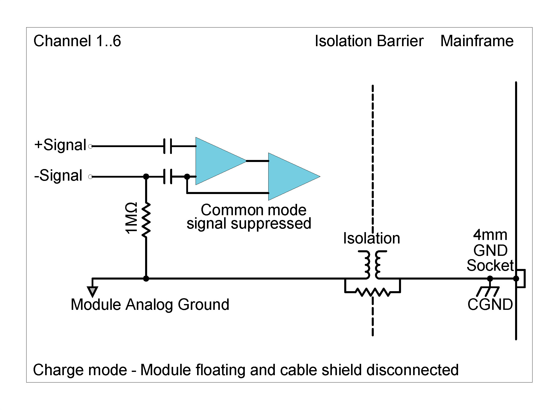
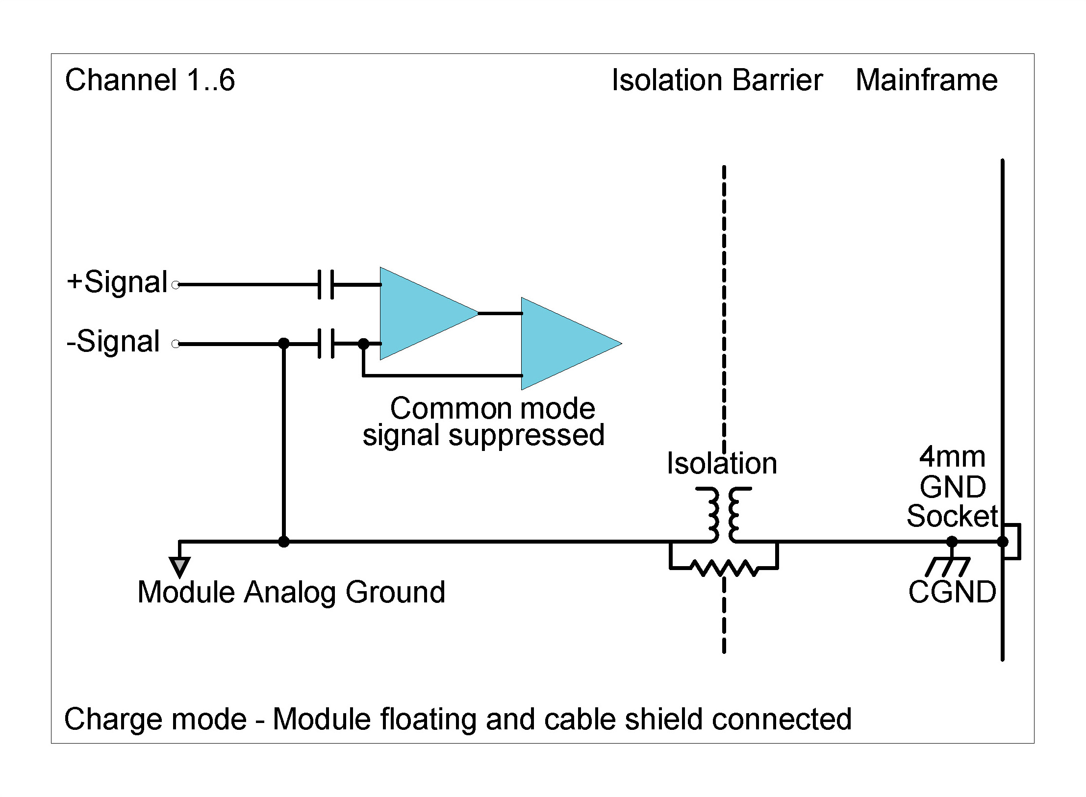
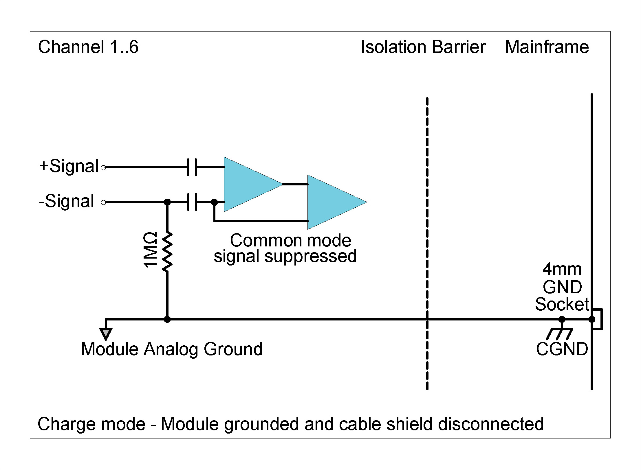
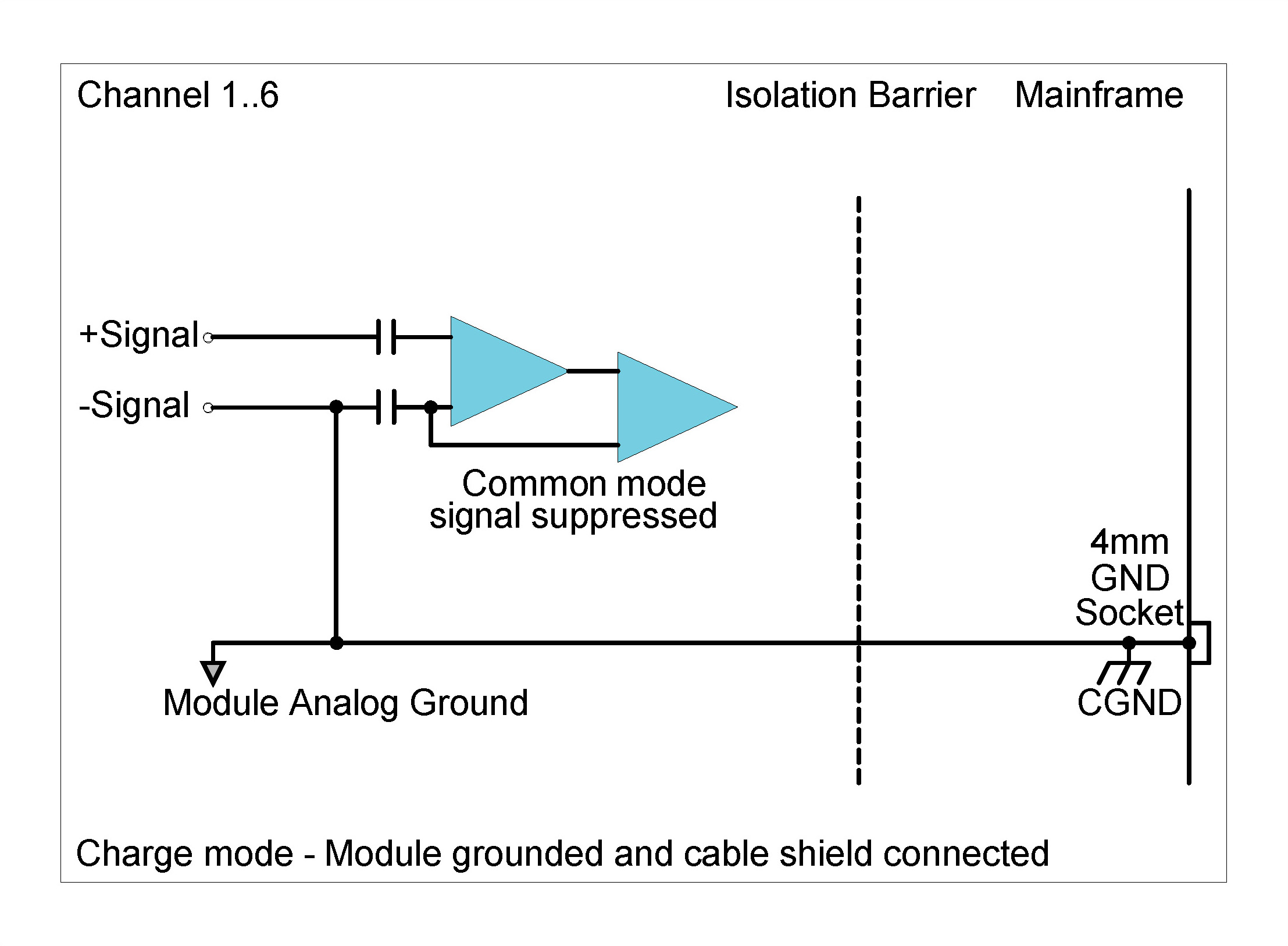
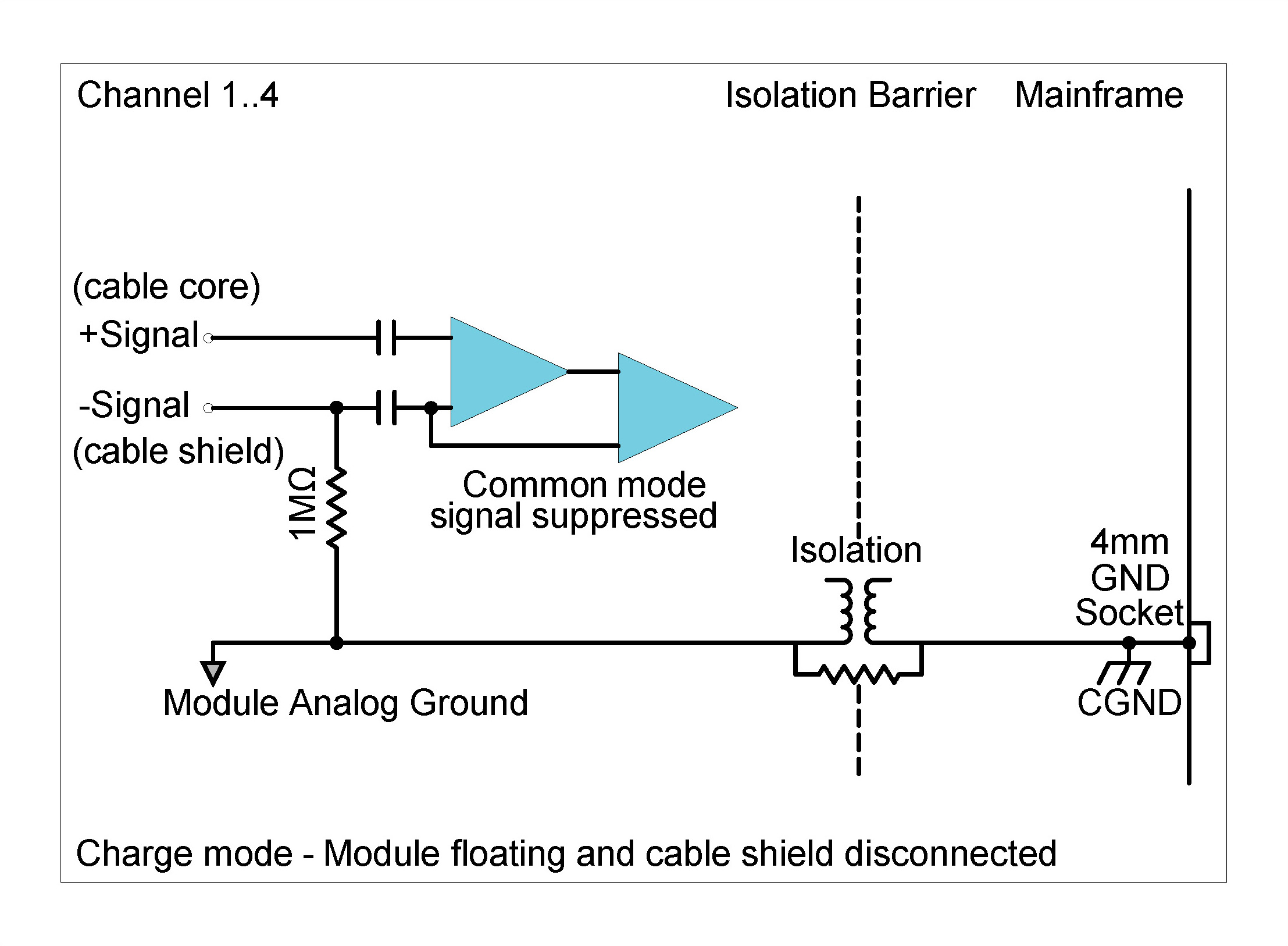
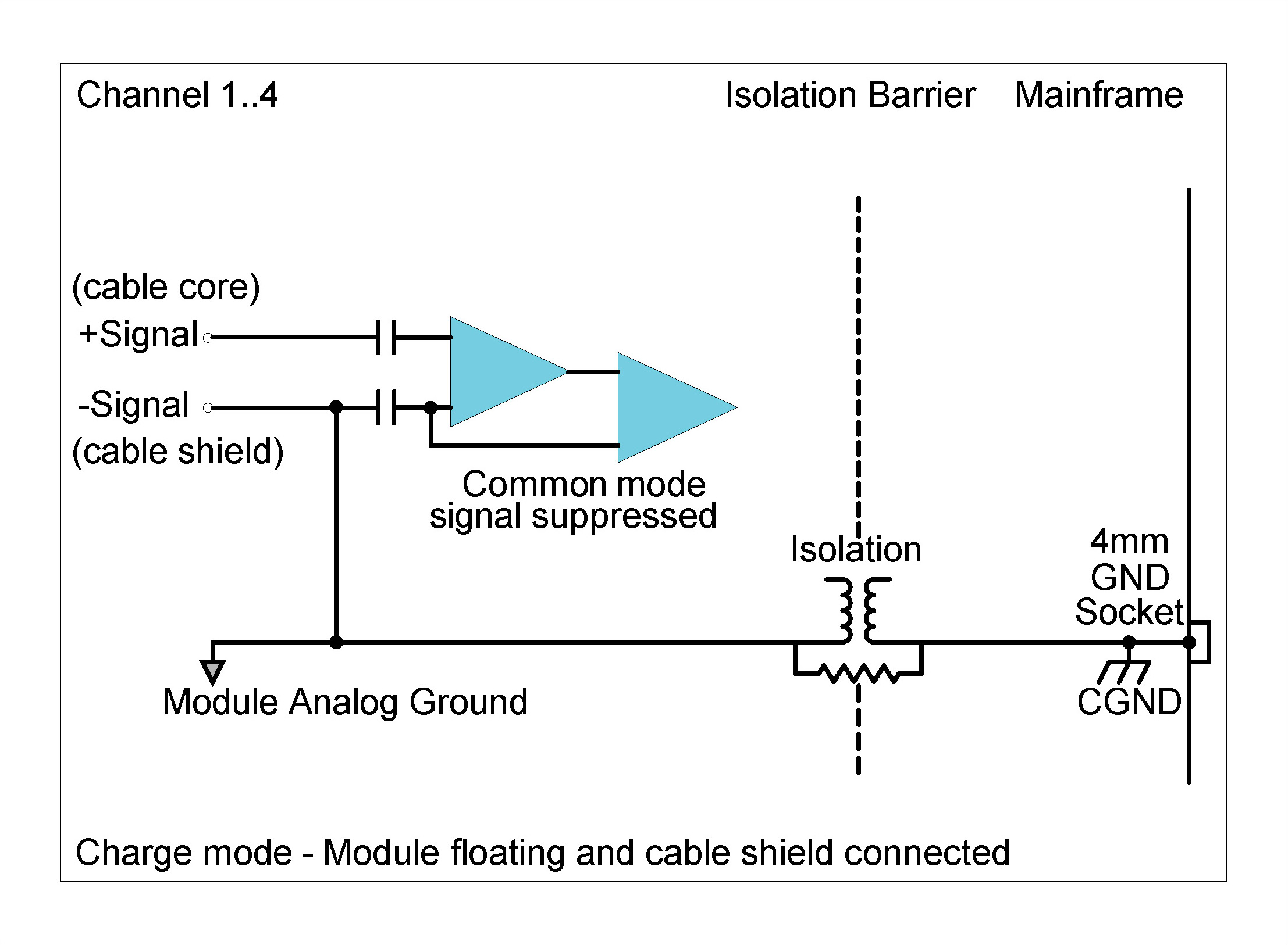
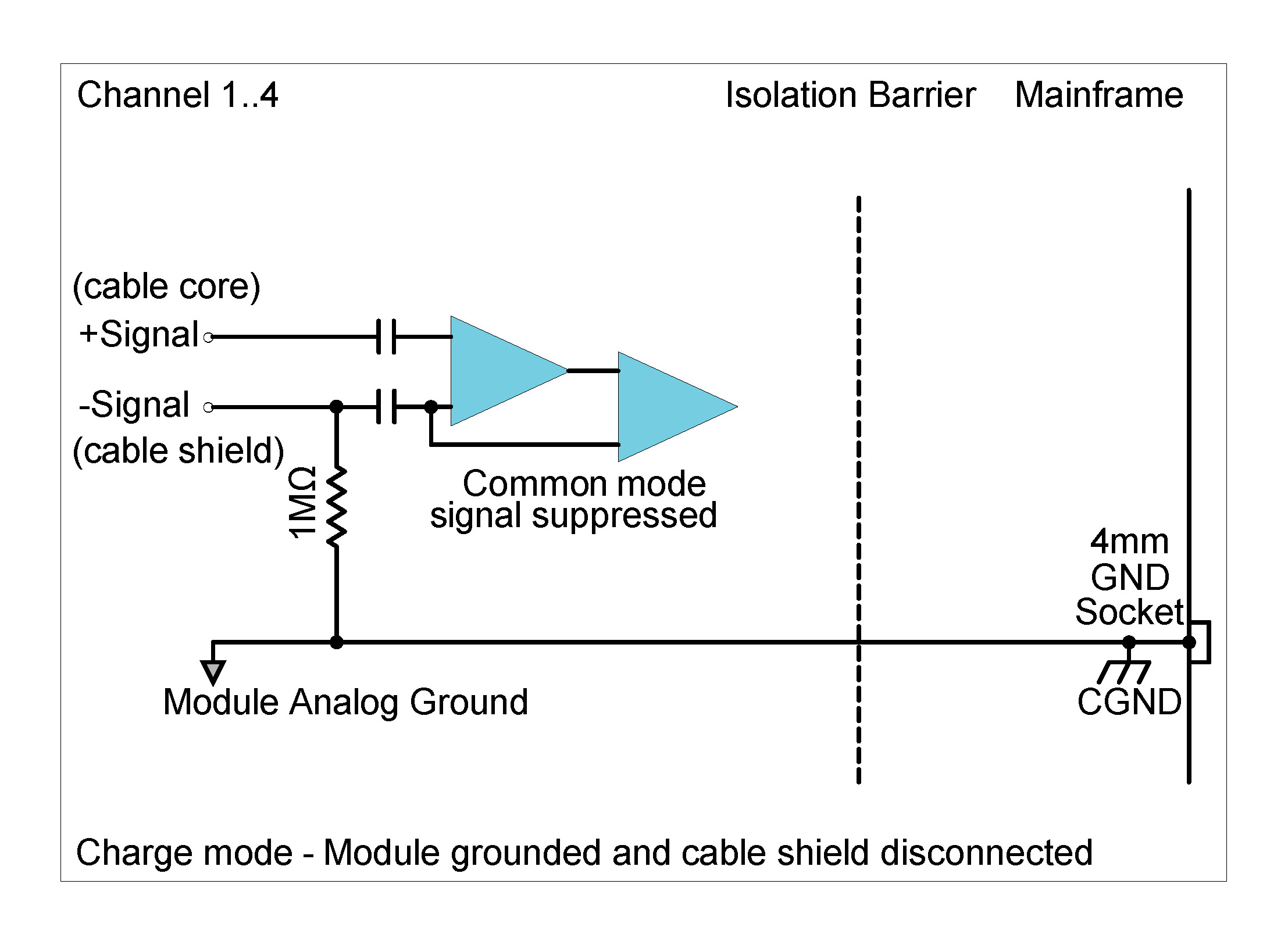
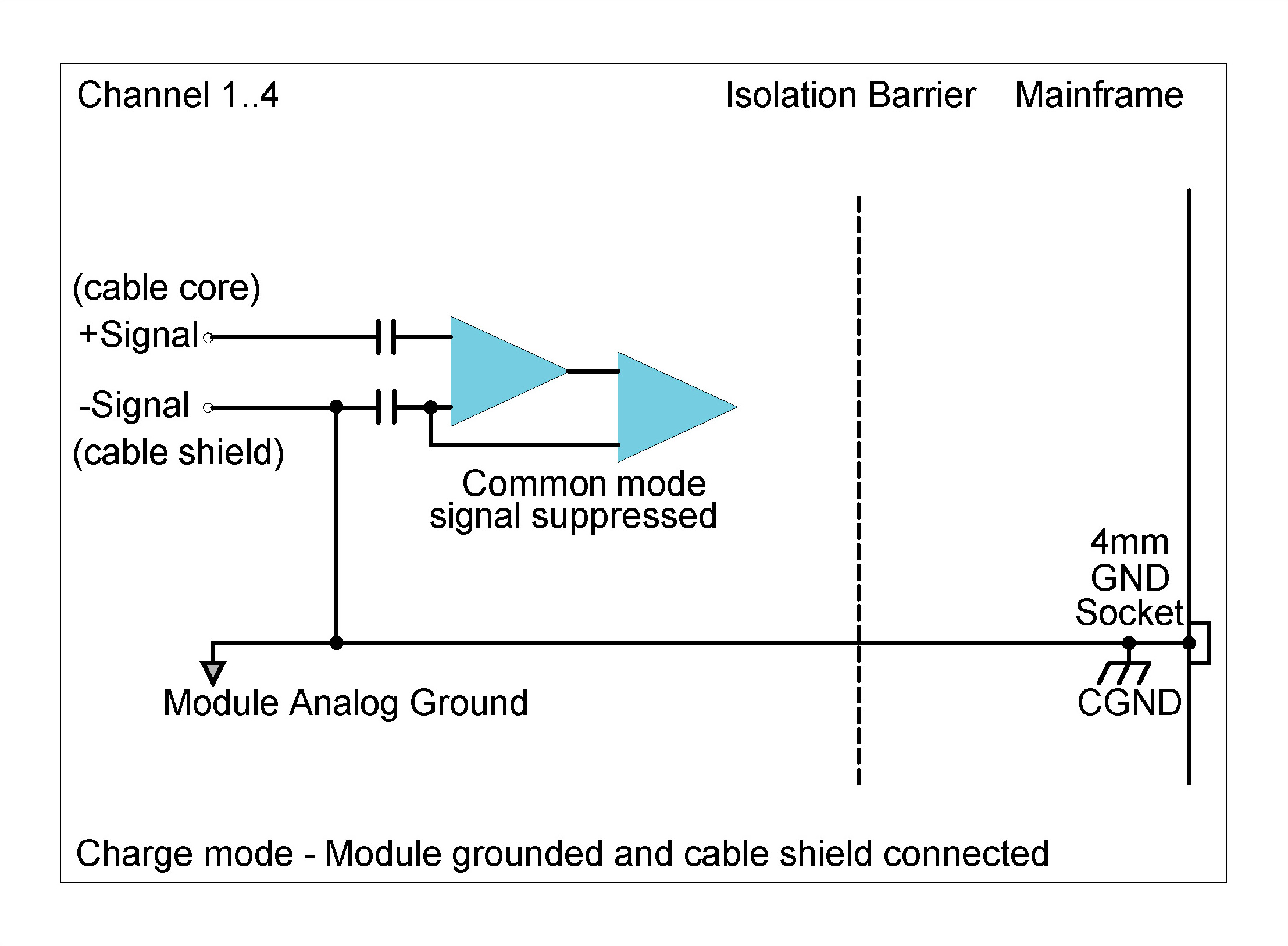
| Input Biasing Settings | Single-Ended Float | Cable Shield Disconnected | Negative signal input (cable shield) connected to floating ground through 1 MΩ |
| Cable Shield Connected | Negative signal input (cable shield) connected to floating ground | ||
| Single-Ended GND | Cable Shield Disconnected | Negative signal input (cable shield) connected to ground through 1 MΩ | |
| Cable Shield Connected | Negative signal input (cable shield) connected to ground | ||
|
Digital Low-Pass Filter Filter scales with sampling rate |
Passband | fs x 0.433 Hz | |
| Stopband | fs x 0.499 Hz | ||
| Passband Ripple | ±0.005 dB | ||
| Stopband Attenuation | 105 dB | ||
|
Phase Accuracy for Charge Mode All channels in Charge mode |
Typical6,7 | ±0.5° at 10 kHz | |
| Phase Accuracy for Charge and Voltage Input / ICP® ModeChannels in combination of Charge and Voltage Input / ICP® mode | Typical8 | ±0.7° at 10 kHz | |
CHX42X Charge Input Mode Specifications
6Measured in 10 V range at 102.4 kSa/s with all channels in
charge mode.
7 Valid for charge mode sensitivities 1 mV/pC and 0.1
mV/pC.
8 Measured in 10 V range at 102.4 kSa/s with 3 channels in
charge mode and 3 channels in voltage input Mode
|
Charge Mode AC Voltage Accuracy Measured at 1 kHz |
Input Range(Peak) | Sensitivity Range | % Range | ||
| ±100 mV | 0.01 mV/pC | 3.0 % | |||
| 0.1 mV/pC | 3.1 % | ||||
| 1 mV/pC | 2.7 % | ||||
| ±1 V | 0.01 mV/pC | 2.5 % | |||
| 0.1 mV/pC | 2.7 % | ||||
| 1 mV/pC | 1.9 % | ||||
| ±10 V | 0.01 mV/pC | 2.5 % | |||
| 0.1 mV/pC | 2.6 % | ||||
| 1 mV/pC | 2.1 % | ||||
|
Charge Mode Noise Measured open input with 1 mV/pC sensitivity range |
Input Range (Peak) | Guaranteed | Typical | ||
| 10 Hz to 22 kHz | ±100 mV | < 6.0 µVrms | < 5.0 µVrms | ||
| 10 Hz to 44.3 kHz | < 10 µVrms | < 8.0 µVrms | |||
| 10 Hz to 22 kHz | ±1 V | < 7.0 µVrms | < 6.5 µVrms | ||
| 10 Hz to 44.3 kHz | < 14.9 µVrms | < 12.1 µVrms | |||
| 10 Hz to 22 kHz | ±10 V | < 40 µVrms | < 35 µVrms | ||
| 10 Hz to 44.3 kHz | < 125 µVrms | < 89 µVrms | |||
| Charge Mode Noise Measured open input with 0.1 mV/pC sensitivity range | Input Range (Peak) | Guaranteed | Typical | ||
| 10 Hz to 22 kHz | ±100 mV | < 6.0 µVrms | < 5.5 µVrms | ||
| 10 Hz to 44.3 kHz | < 8.0 µVrms | < 7.5 µVrms | |||
| 10 Hz to 22 kHz | ±1 V | < 7.5 µVrms | < 6.5 µVrms | ||
| 10 Hz to 44.3 kHz | < 9.0 µVrms | < 8.5 µVrms | |||
| 10 Hz to 22 kHz | ±10 V | < 90 µVrms | < 65 µVrms | ||
| 10 Hz to 44.3 kHz | < 140 µVrms | < 105 µVrms | |||
|
Charge Mode Noise Measured open input with 0.01 mV/pC sensitivity range |
Input Range (Peak) | Guaranteed | Typical | ||
| 10 Hz to 22 kHz | ±100 mV | < 10 µVrms | < 9.5 µVrms | ||
| 10 Hz to 44.3 kHz | < 8.0 µVrms | < 7.0 µVrms | |||
| 10 Hz to 22 kHz | ±1 V | < 8.5 µVrms | < 7.5 µVrms | ||
| 10 Hz to 44.3 kHz | < 9.0 µVrms | < 8.5 µVrms | |||
| 10 Hz to 22 kHz | ±10 V | < 45 µVrms | < 35 µVrms | ||
| 10 Hz to 44.3 kHz | < 50 µVrms | < 40 µVrms | |||
| Charge Mode Dynamic Range9Measured from 50 Hz to 0.40 x fs | Input Range (Peak) | Typical | |||
| 0.01 mV/pC sensitivity range | 0.1 mV/pC sensitivity range | 1 mV/pC sensitivity range | |||
| ±100 mV | > 110 dB | > 110 dB | > 110 dB | ||
| ±1 V | > 130 dB | > 130 dB | > 130 dB | ||
| ±10 V | > 130 dB | > 130 dB | > 130 dB | ||
| Charge Mode Amplitude FlatnessMeasured from 50 Hz to 0.40 x fs | Sampling Rate (fs) | Input Range (Peak) | Attenuation (input signal level 100% of full range) | ||
| 0.01 mV/pC sensitivity range | 0.1 mV/pC sensitivity range | 1 mV/pC sensitivity range | |||
| 51.2 kSa/s | ±100 mV | − 0.35 dB | − 0.24 dB | − 0.48 dB | |
| 102.4 kSa/s | − 0.45 dB | − 0.77 dB | − 1.45 dB | ||
| 51.2 kSa/s | ±1 V | − 0.18 dB | − 0.22 dB | − 0.39 dB | |
| 102.4 kSa/s | − 0.76 dB | − 0.76 dB | − 0.96 dB | ||
| 51.2 kSa/s | ±10 V | − 0.22 dB | − 0.21 dB | − 0.41 dB | |
| 102.4 kSa/s | − 0.75 dB | − 0.80 dB | − 0.99 dB | ||
CHX42X Charge Input Mode Specifications 9 Dynamic range calculated at sampling rate of 51.2 kSa/s, with a 4096-point FFT.
Specification number: SP200300, Release 1.3. Module settings and measurement conditions that were used during specification measurements are available on request.
Functionality per Channel
Connector layout
On the front panel of the CHS42X a connector layout description can be found.
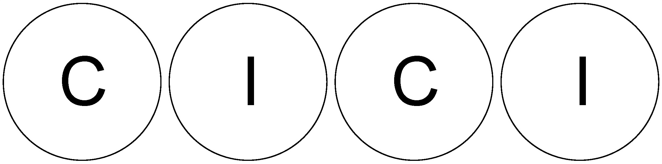
Connectors marked with an  will accept ICP® as
well as voltage input signals. Connectors marked with a
will accept ICP® as
well as voltage input signals. Connectors marked with a  are capable of accepting charge signals.
ICP® Accelerometer Connections per Module
The CHS42X can accept inputs from single ICP® accelerometers as well as triaxial ICP® accelerometers. The connectors on the front panel are ideally designed to connect to two triaxial sensors per Module. The LEMO® 9-way EHG.0B connectors Module pin definition indicates where the signal connections of each X, Y and Z and the common return of the triaxial sensor can be connected.
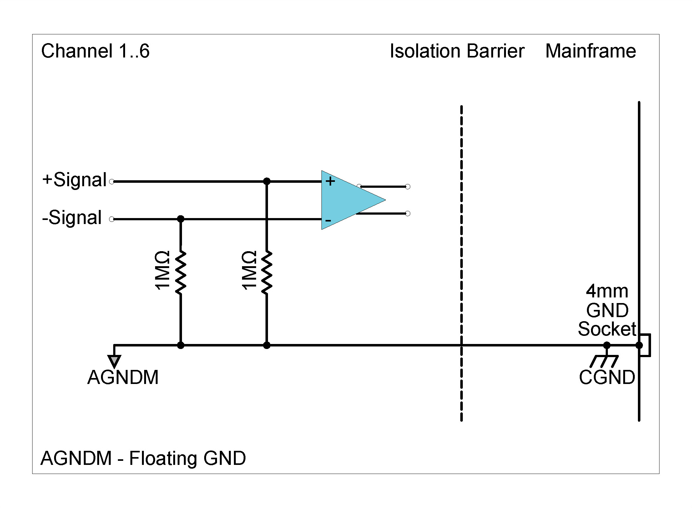
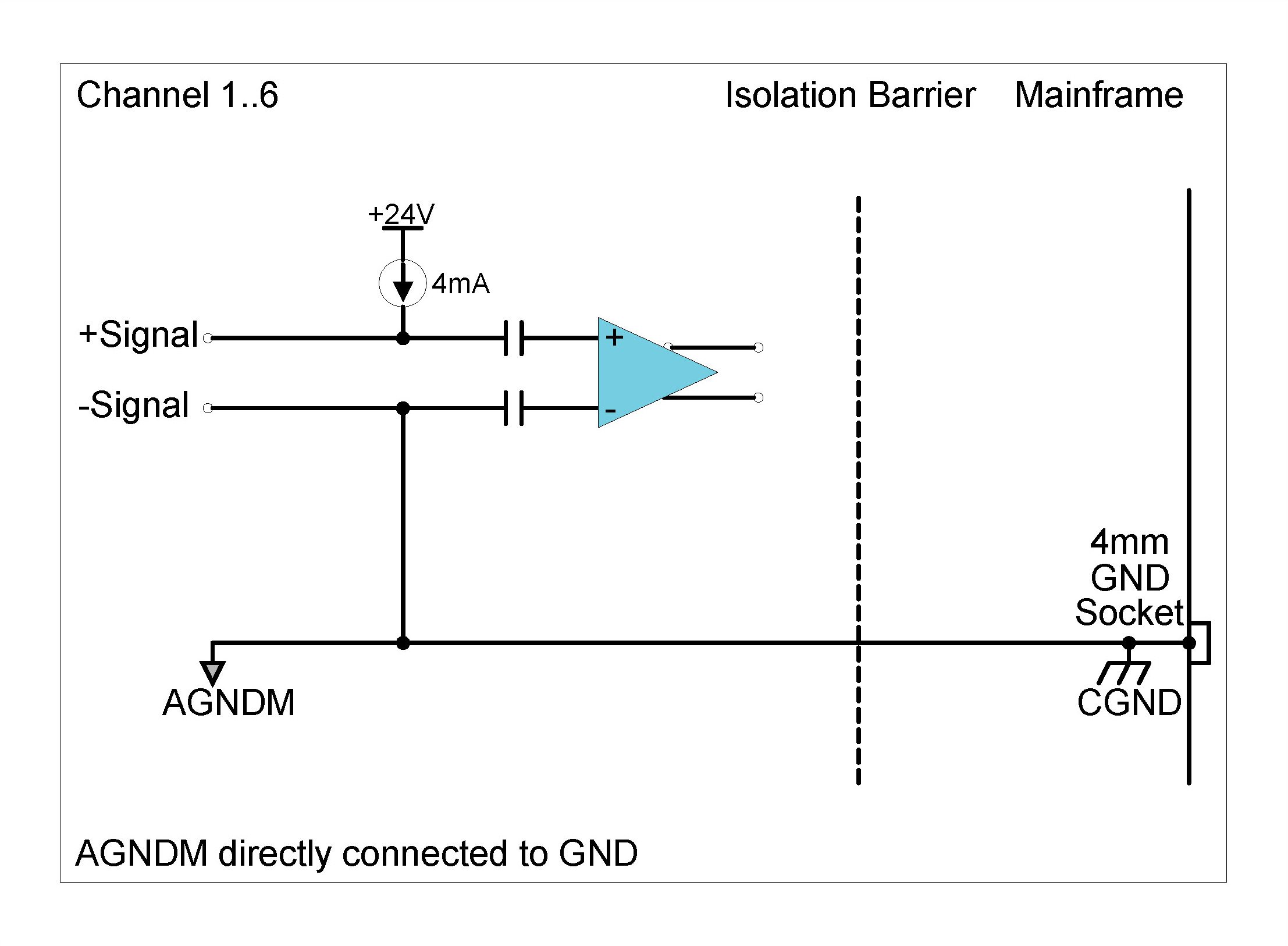
Grounding options ALI mode (Voltage Input mode)
There are four ALI mode grounding options available on the CHS42X:
Grounding Diagrams: ALI mode (Voltage input mode)

Although each channel in the CHS42X can be set individually as to its grounding type, enabling the ground option on any one channel will cause the isolation barrier of the module to be bridged (i.e., on all six channels AGNDM will be directly connected to CGND).
Grounding options Charge mode
The CHS42X offers 4 grounding options. The grounding options are provided for reducing electromagnetic interference (EMI) that might be present on the sensor cables.
| Module | Cable Shield Connected | Industry Name | Shield to Chassis |
|---|---|---|---|
| *Floating | *No | Floating | 1 MΩ + 10 kΩ |
| Floating | Yes | - | 10 kΩ |
| Grounded | No | - | 1 MΩ |
| Grounded | Yes | Single-Ended | ~20 Ω |
CHS42X Module charge mode grounding options
*Default setting on Module startup. This combination provides a path for Electrostatic Discharge (ESD) to slowly discharge and will provide some protection against rapid ESD events that could damage the sensitive charge inputs.
Grounding Diagrams: Charge mode
Excitation Diagrams: ICP® Mode
The CHS42X can facilitate an ICP® input mode with a 4 mA current excitation. The Biasing settings are independent of the grounding options. The following table shows the different possible settings for the ICS42 Module in ICP® input mode:
| Excitation voltage | Biasing settings | Grounding options |
|---|---|---|
| 24 V (Asymmetrical) | Differential or single-ended | Ground or Floating ground |
CHS42X Module Settings in ICP® input mode with 4 mA current excitation
Description
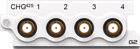
The CHG42S Module has 4 independent input channels for Quartz or Piezoelectric Ceramic sensors. These sensors are typically used when improved signal performance such as low noise and low distortion is required or where high temperature or nuclear radiation prevents the use of ICP® based sensors. Various grounding options allow for low noise measurements regardless of external grounding constraints. The Module can be used:
| Front Panel | Connector Information and Pin Definitions |
|---|---|
 |
 |
CHG42S with 10-32 Microdot connectors Module Pin Definition when looking into the front panel’s connector or at the rear of the cable’s connector
ESD WARNING
The CHG42S Module inputs are sensitive to ESD damage. Always take care to discharge any additional static electricity that might have built up on a cable and connector before making contact with the CHG42S Module.
Features
Please note:The features and specifications may
vary based on the software package utilized with the
DECAQ
CHG42S Specifications
| Interface | For piezoelectric sensors | ||
| Voltage Amplifier Range (Peak) | ±100 mV, ±1 V, ±10 V | ||
| Input Charge Range (Peak) | 0.1 mV/pC | ±100,000 pC | |
| 1 mV/pC | ±10,000 pC | ||
| 10 mV/pC | ±1,000 pC | ||
| -3 dB High-Pass Frequency | 0.1 mV/pC | 0.016 Hz | |
| 1 mV/pC | 0.016 Hz | ||
| 10 mV/pC | 0.16 Hz | ||
| Other Sampling Rates | Available through digital LP filters and decimation | ||
| Optional Programmable Digital IIR Filter |
Bandpass/stop : 6 dB/octave High/Low-pass : 12 dB/octave |
||
| Optional First Order High-Pass Filter | -3 dB @ 1 Hz | ||
| Module Calibration | Internal amplitude calibration | ||
| Protection | 1 kΩ series (inline) | ||
| Galvanic Isolation | 50 V | ||
| Bandwidth | DC to 90 kHz | ||
| Maximum Sampling Rate (fs) per Channel | 204.8 kSa/s | ||
| A/D Conversion | 24-bit | ||
| Data Transfer | 16/24-bit | ||
| Input Voltage Ranges (Peak) | ±100 mV; ±1 V; ±10 V | ||
| Sensitivity Ranges (Peak) | 0.1 mV/pC; 1 mV/pC; 10 mV/pC | ||
| Input Biasing Settings | Single-Ended Float | Cable Shield Disconnected | Negative signal input (cable shield) connected to floating ground through 1 MΩ |
| Cable Shield Connected | Negative signal input (cable shield) connected to floating ground | ||
| Single-Ended GND | Cable Shield Disconnected | Negative signal input (cable shield) connected to floating ground | |
| Cable Shield Connected | Negative signal input (cable shield) connected to ground | ||
|
Digital Low-Pass Filter Filter scales with sampling rate |
Passband | fs x 0.45 Hz | |
| Stopband | fs x 0.55 Hz | ||
| Passband Ripple | ±0.005 dB | ||
| Stopband Attenuation | 100 dB | ||
|
Phase Accuracy Channels in similar range |
Typical1 | < 0.5° at 10 kHz | |
1 Measured in 10 V range at 204.8 kSa/s
|
AC Voltage Accuracy Measured at 1 kHz |
Input Range (Peak) | Sensitivity Range | % Range Typical | ||
| ±100 mV | 0.1 mV/pC | 3.1 % | |||
| 1 mV/pC | 2.7 % | ||||
| 10 mV/pC | 2.7 % | ||||
| ±1 V | 0.1 mV/pC | 2.7 % | |||
| 1 mV/pC | 1.9 % | ||||
| 10 mV/pC | 2.5 % | ||||
| ±10 V | 0.1 mV/pC | 2.6 % | |||
| 1 mV/pC | 2.1 % | ||||
| 10 mV/pC | 2.6 % | ||||
|
Noise Measured open input with 0.1 mV/pC sensitivity range |
Input Range (Peak) | Guaranteed | Typical | ||
| 10 Hz to 23 kHz | ±100 mV | < 50 µVrms | < 46 µVrms | ||
| 10 Hz to 49 kHz | < 73 µVrms | < 68 µVrms | |||
| 10 Hz to 90 kHz | < 160 µVrms | < 144 µVrms | |||
| 10 Hz to 23 kHz | ±1 V | < 109 µVrms | < 81 µVrms | ||
| 10 Hz to 49 kHz | < 140 µVrms | < 116 µVrms | |||
| 10 Hz to 90 kHz | < 1085 µVrms | < 924 µVrms | |||
| 10 Hz to 23 kHz | ±10 V | < 460 µVrms | < 409 µVrms | ||
| 10 Hz to 49 kHz | < 1175 µVrms | < 859 µVrms | |||
| 10 Hz to 90 kHz | < 10816 µVrms | < 9114 µVrms | |||
|
Noise Measured open input with 1 mV/pC sensitivity range |
Input Range (Peak) | Guaranteed | Typical | ||
| 10 Hz to 23 kHz | ±100 mV | < 8.8 µVrms | < 6.2 µVrms | ||
| 10 Hz to 49 kHz | < 10 µVrms | < 8 µVrms | |||
| 10 Hz to 90 kHz | < 17.8 µVrms | < 15.3 µVrms | |||
| 10 Hz to 23 kHz | ±1 V | < 11.4 µVrms | < 8.5 µVrms | ||
| 10 Hz to 49 kHz | < 14.9 µVrms | < 12.1 µVrms | |||
| 10 Hz to 90 kHz | < 107 µVrms | < 92 µVrms | |||
| 10 Hz to 23 kHz | ±10 V | < 46 µVrms | < 41 µVrms | ||
| 10 Hz to 49 kHz | < 125 µVrms | < 89 µVrms | |||
| 10 Hz to 90 kHz | < 1077 µVrms | < 910 µVrms | |||
|
Noise Measured open input with 10 mV/pC sensitivity range |
Input Range (Peak) | Guaranteed | Typical | ||
| 10 Hz to 23 kHz | ±100 mV | < 9.1 µVrms | < 4.4 µVrms | ||
| 10 Hz to 49 kHz | < 9 µVrms | < 4.6 µVrms | |||
| 10 Hz to 90 kHz | < 9.1 µVrms | < 5.1 µVrms | |||
| 10 Hz to 23 kHz | ±1 V | < 8.9 µVrms | < 4.4 µVrms | ||
| 10 Hz to 49 kHz | < 8.8 µVrms | < 4.6 µVrms | |||
| 10 Hz to 90 kHz | < 8.2 µVrms | < 7.3 µVrms | |||
| 10 Hz to 23 kHz | ±10 V | < 8.6 µVrms | < 5.8 µVrms | ||
| 10 Hz to 49 kHz | < 13.2 µVrms | < 9.3 µVrms | |||
| 10 Hz to 90 kHz | < 108 µVrms | < 91 µVrms | |||
|
Charge Mode Dynamic Range2 Measured from 50 Hz to 0.40 x fs |
Input Range (Peak) | Typical | |||
| 0.01 mV/pC sensitivity range | 0.1 mV/pC sensitivity range | 1 mV/pC sensitivity range | |||
| ±100 mV | > 110 dB | > 110 dB | > 90 dB | ||
| ±1 V | > 130 dB | > 130 dB | > 110 dB | ||
| ±10 V | > 130 dB | > 130 dB | > 130 dB | ||
|
Amplitude Flatness Relative to 1 kHz Measured up to 0.39 x fs |
Sampling Rate (fs) | Input Range (Peak) |
Attenuation Input signal level 100 % of full range |
||
| 0.1 mV/pC sensitivity range | 1 mV/pC sensitivity range | 10 mV/pC sensitivity range | |||
| 51.2 kSa/s | ±100 mV | -0.12 dB | -0.19 dB | -0.88 dB | |
| 102.4 kSa/s | -0.44 dB | -0.70 dB | -2.88 dB | ||
| 204.8 kSa/s | -1.91 dB | -2.40 dB | -7.43 dB | ||
| 51.2 kSa/s | ±1 V | -0.15 dB | -0.14 dB | -0.86 dB | |
| 102.4 kSa/s | -0.47 dB | -0.52 dB | -2.82 dB | ||
| 204.8 kSa/s | -1.57 dB | -1.86 dB | -7.07 dB | ||
| 51.2 kSa/s | ±10 V | -0.14 dB | -0.14 dB | -0.79 dB | |
| 102.4 kSa/s | -0.45 dB | -0.51 dB | -2.66 dB | ||
| 204.8 kSa/s | -1.50 dB | -2.81 dB | -6.84 dB | ||
|
Crosstalk Measured with 0.1 mV/pC sensitivity range |
Input Range (Peak) | Guaranteed Range | Typical | ||
| ±100 mV | 83 dB | 88 dB | |||
| ±1 V | 93 dB | 98 dB | |||
| ±10 V | 90 dB | 95 dB | |||
|
Crosstalk Measured with 1 mV/pC sensitivity range |
Input Range (Peak) | Guaranteed Range | Typical | ||
| ±100 mV | 60 dB | 65 dB | |||
| ±1 V | 83 dB | 88 dB | |||
| ±10 V | 85 dB | 90 dB | |||
|
Crosstalk Measured with 10 mV/pC sensitivity range |
Input Range (Peak) | Guaranteed Range | Typical | ||
| ±100 mV | 41 dB | 46 dB | |||
| ±1 V | 62 dB | 67 dB | |||
| ±10 V | 67 dB | 72 dB | |||
CHG42S Specifications
2 Dynamic range
calculated at sampling rate of 51.2 kSa/s, with a 4096-point
FFT.
Specification number: SP160200, Release 1.8. The Module settings
and measurement conditions that were used during specification
measurements are available on request.
Functionality per Channel
WARNING
When using Endevco cables it is recommended to remove the rubber O-ring on the CHG42S Module 10-32 connector as this could cause an intermittent electrical connection between the pin on the cable and the Module connector.
The CHG42S offers 4 grounding options. The grounding options are provided for reducing electromagnetic interference (EMI) that might be present on the sensor cables.
| Module | Cable Shield Connected | Industry Name | Shield to Chassis |
|---|---|---|---|
| *Floating | *No | Floating | 1 MΩ + 10 kΩ |
| Floating | Yes | - | 10 kΩ |
| Grounded | No | - | 1 MΩ |
| Grounded | Yes | Single-Ended | ~20 Ω |
Grounding options
*Default setting on Module startup. This combination provides a path for Electrostatic Discharge (ESD) to slowly discharge and will provide some protection against rapid ESD events that could damage the sensitive charge inputs.
Description
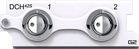
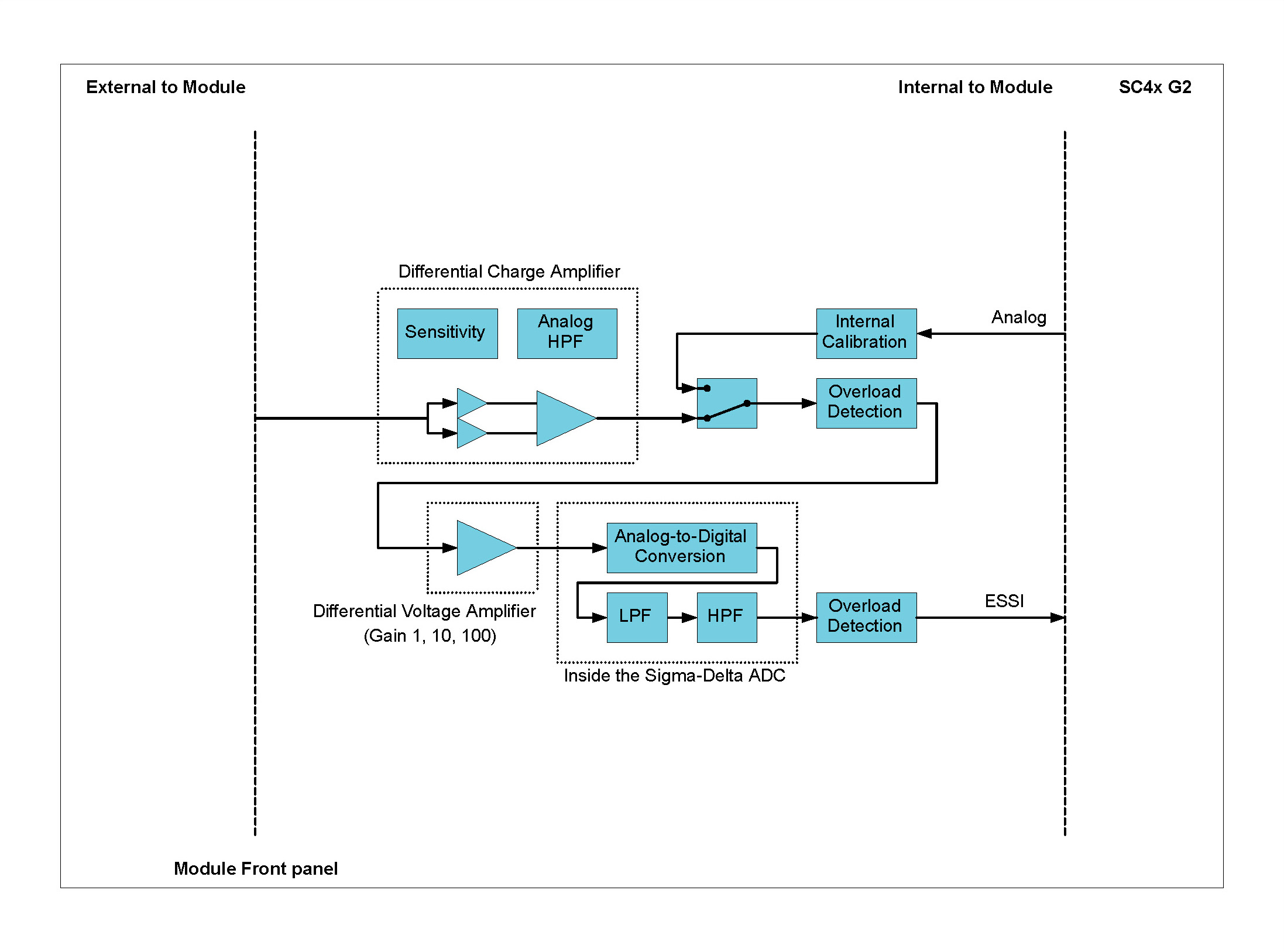
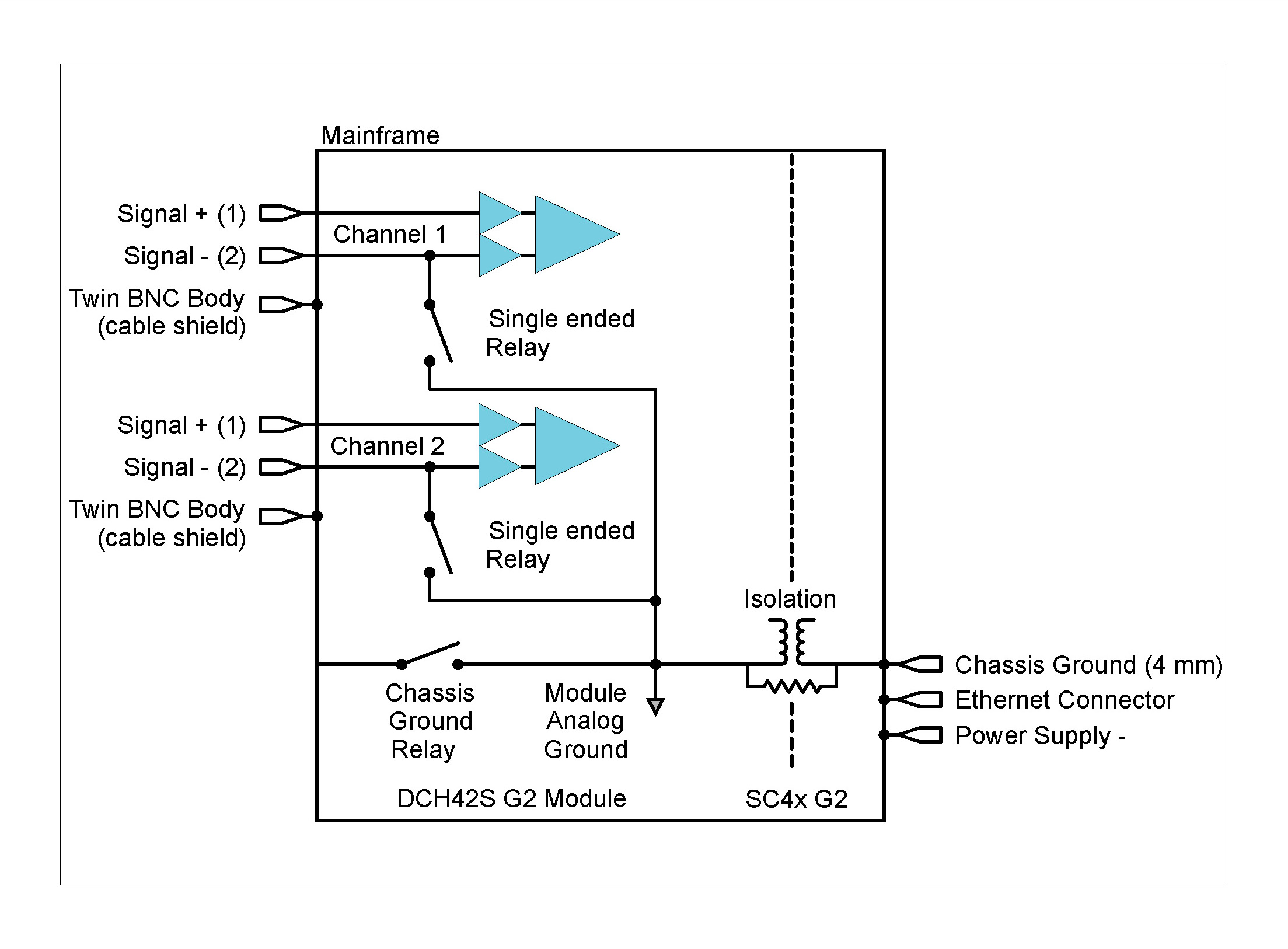
The DCH42S Module has 2 independent differential input channels for Quartz or Piezoelectric Ceramic sensors. These sensors are typically used when improved signal performance such as low noise and low distortion is required or where high temperature and nuclear radiation prevents the use of ICP® based sensors. Additionally, a differential charge measurement offers further noise immunity and higher bandwidth and is particularly suited to applications using long cables. The Module can be used:
| Front Panel | Connector Information and Pin Definitions |
|---|---|
 |
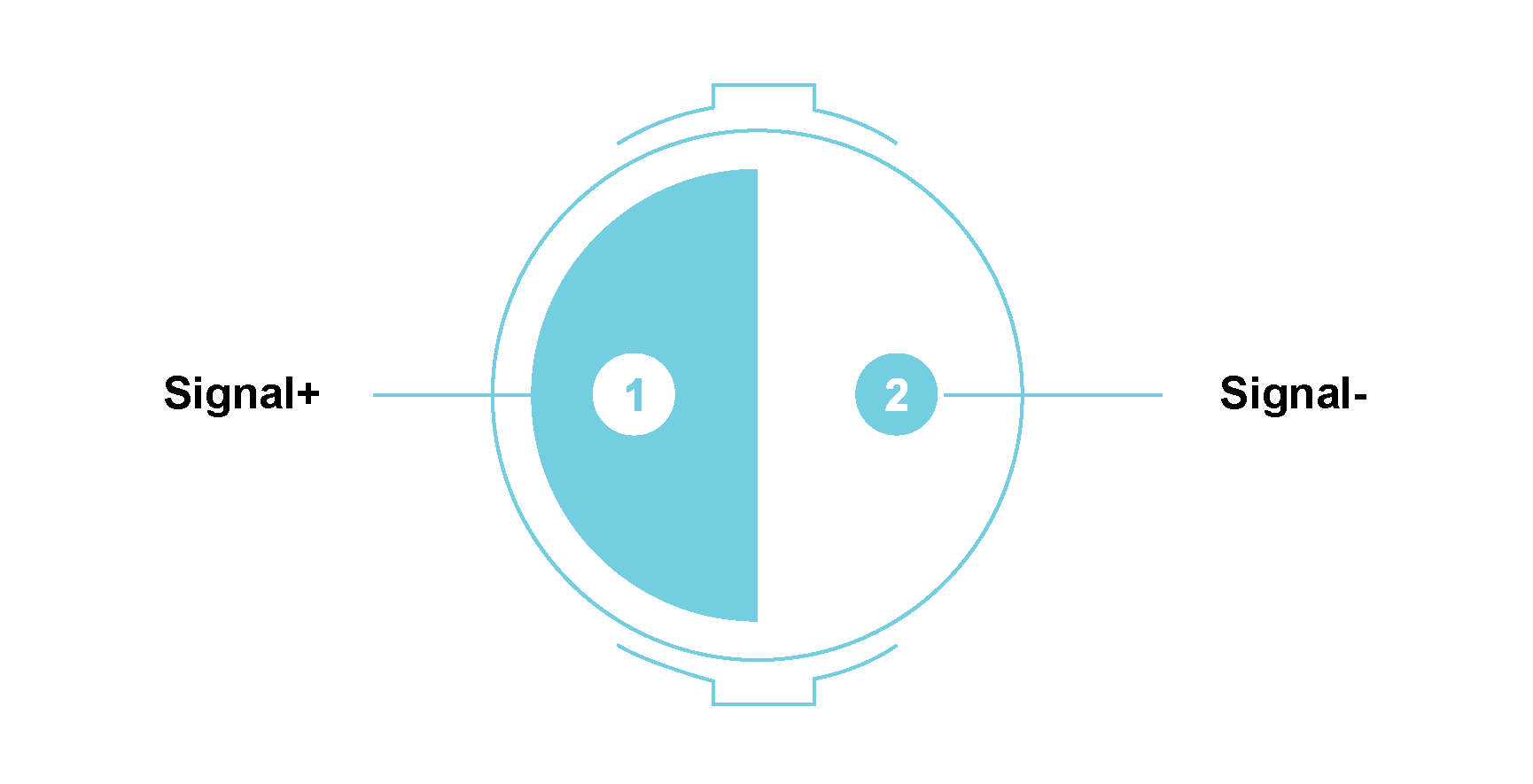 |
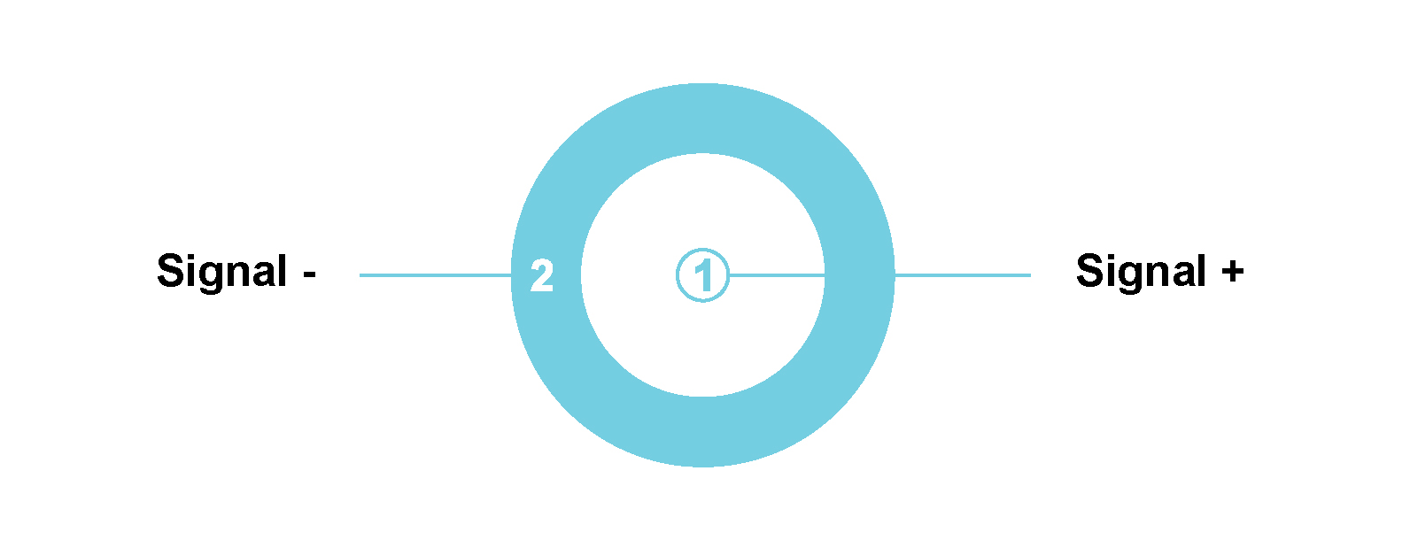
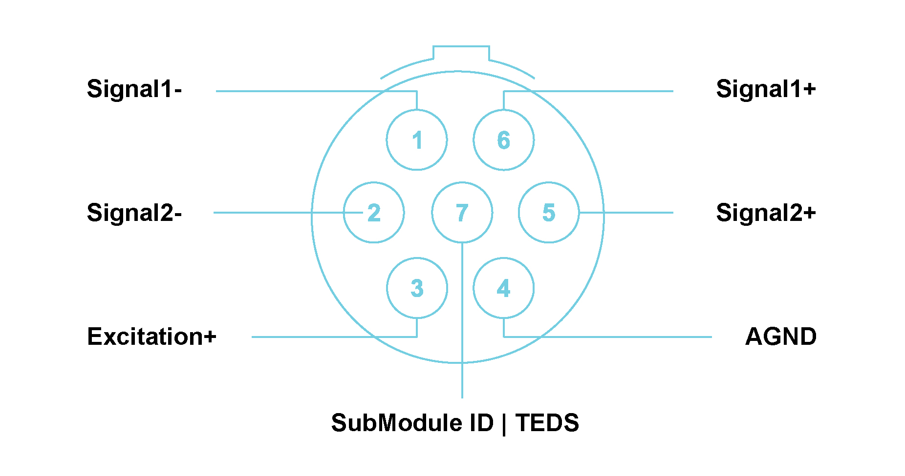
DCH42S with 31-2225 twin BNC connectors Module Pin Definition (when looking into the front panel’s connector or at the rear of the cable’s connector)
ESD WARNING
The DCH42S Module inputs are sensitive to ESD damage. Always take care to discharge any additional static electricity that might have built up on a cable and connector before making contact with the DCH42S Module.
Features
Please note:The features and specifications may vary based on the software package utilized with the DECAQ
DCH42S Specifications
| Interface | For piezoelectric sensors | ||
| Voltage Amplifier Ranges | ±100 mV, ±1 V, ±10 V (peak) | ||
| Input Charge Ranges | Single-Ended Mode | 0.1 mV/pC | ±100 000 pC (peak) |
| 1 mV/pC | ±10 000 pC (peak) | ||
| Differential Mode | 0.2 mV/pC | ±5 000 pC (peak) | |
| 2 mV/pC | ±50 000 pC (peak) | ||
| -3dB High Pass Frequency | Single-Ended Mode | 0.1 mV/pC | 0.16 Hz or 0.016 Hz |
| 1 mV/pC | 1.6 Hz or 0.16 Hz | ||
| Differential Mode | 0.2 mV/pC | 0.16 Hz or 0.016 Hz | |
| 2 mV/pC | 1.6 Hz or 0.16 Hz | ||
|
Phase Accuracy Channels in similar range |
Typical1 | < 0.5° at 10 kHz | |
| Other Sampling Rates | Available through digital LP filters and decimation | ||
| Optional Programmable Digital IIR Filter |
Band pass/stop : 6 dB/octave High/Low pass : 12 dB/octave |
||
| Optional First Order High-Pass Filter | -3 dB @ 1 Hz | ||
| Module Calibration | Internal amplitude calibration | ||
| Protection | 1 kΩ series (inline) | ||
| Galvanic Isolation | 50 V | ||
|
Digital Low-Pass Filter Filter scales with sampling rate |
Passband | fs x 0.45 Hz | |
| Stopband | fs x 0.55 Hz | ||
| Passband Ripple | ±0.005 dB | ||
| Stopband Attenuation | 100 dB | ||
DCH42S Specifications
1 Measured in 10 V range at 204.8 kSa/s
Functionality per Channel
Grounding diagram
Description
The THM42 Module contains 8 channels for use with any thermocouple type as well as Pt100 sensors. Remote cold junction compensation is provided through a SubModule (which is thermocouple type specific) whilst linearization is provided in the signal conditioning board. The Module also includes a calibrated 0.2 mA current source for Pt100 sensor excitation.
SubModules are used with the Module which contains a pair of commonly used miniature E, J, K, and T thermocouple connectors (other types available upon request) with cold junction circuitry for thermocouple applications. Another SubModule contains a pair of LEMO® connectors for Pt100 applications. Any combination of applicable SubModules can be connected to the THM42 Module.
The THM42 Module also includes 8 channels for measuring voltage inputs up to ±10 V. The Module can be used:
| Front Panel | Connector Information and Pin Definitions |
|---|---|
 |
 |
THM42 with LEMO® 7-way EHG.0B Module Pin Definition (when looking into the front panel’s connector or at the rear of the cable’s connector)
Features
Please note:The features and specifications may vary based on the software package utilized with the DECAQ
THM42 Specifications
| Input Modes | Thermocouple and Pt100 | |
| Sensors | Any combination of thermocouple and Pt100 but the same type of sensor must be used for each channel pair | |
| Linearization |
Thermocouple linearization for types: Chromel®/Constantan (E, NiCr-CuNi) Iron/Constantan (J, Fe-CuNi) Chromel®/Alumel® (K, NiCr-NiAl) Copper/Constantan (T, Cu-CuNi) |
|
| Excitation | 0.2 mA Excitation current for Pt100 and cold-junction-compensation. Monitored internally for drift and offset errors. | |
| Maximum Common Mode Voltage | ±7 V | |
| Other Sampling Rates | Available through digital LP filters and decimation | |
| SubModules | Cable between Module and sensor wire with housing containing TEDS, cold-junction-compensation and sensor connector. Colour-coded according to thermocouple type. | |
| Module Calibration | Internal amplitude and phase calibration | |
|
Phase Accuracy Channels in similar range |
Typical1 | < 1.5° at 1 kHz |
| Protection | 2 kV ESD | |
| Galvanic Isolation | 50 V | |
THM42 Specifications
1 Measured in 10 V range at 6.4 kSa/s
Functionality per Channel
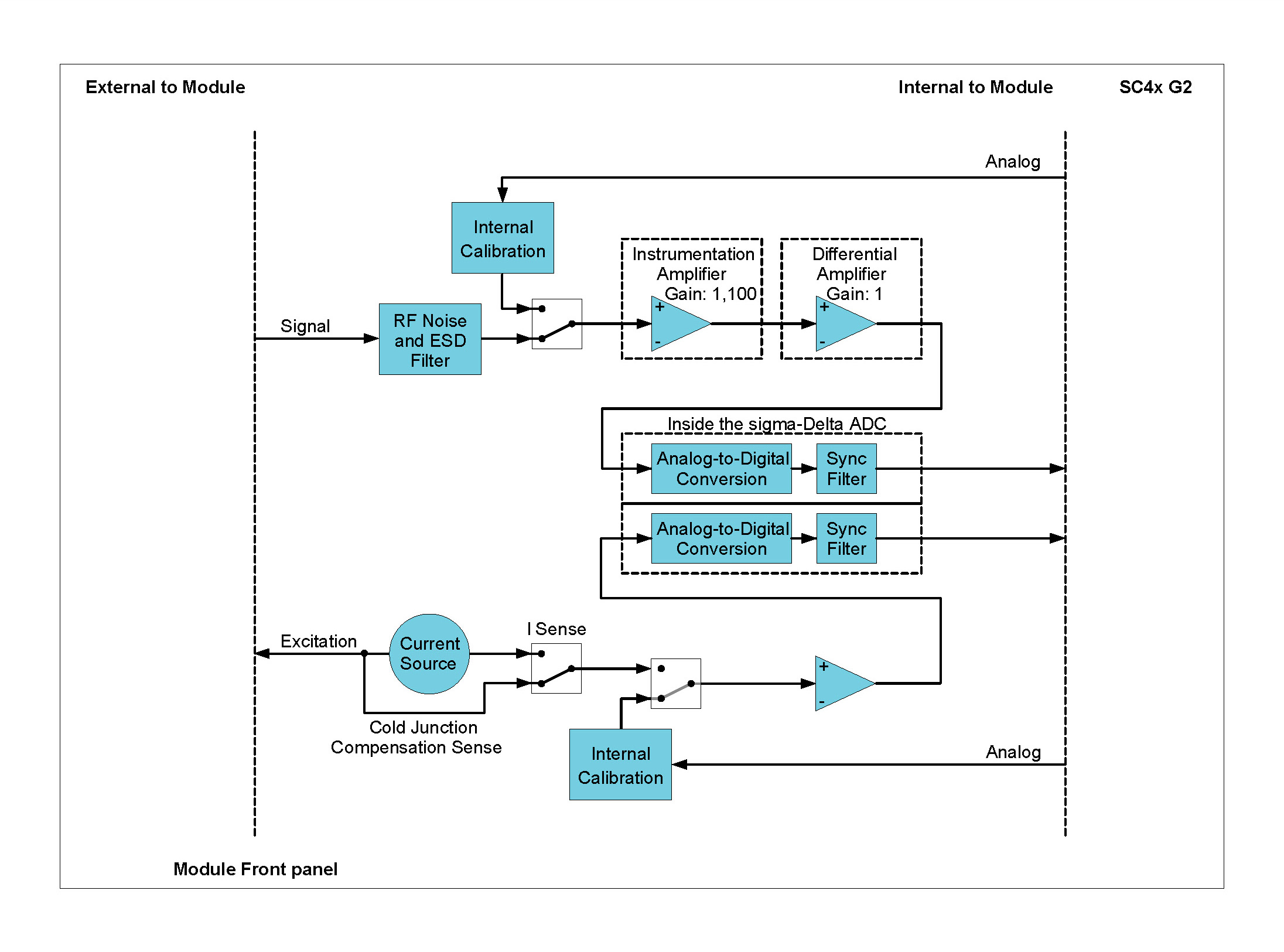
Description
The ICT42 Module is a hybrid Module which combines 2 channels from the ICP42 Module with 2 Tacho input channels. The Tacho channels provide Tacho period measurements with a 20 ns resolution, sampled where the signal intersects its trigger level settings. Triggering of Tacho signals can be set for rising or falling edges with adjustable hysteresis whilst additionally providing AC coupling for sensors with varying DC voltage offsets. A 204.8 kSa/s scope mode is provided to view the Tacho signals in order to assist with the definition of trigger levels. The Module can be used:
| Front Panel | Connector Information and Pin Definitions |
|---|---|
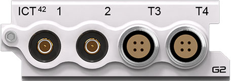 |
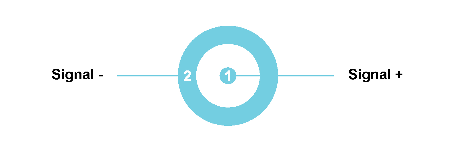 |
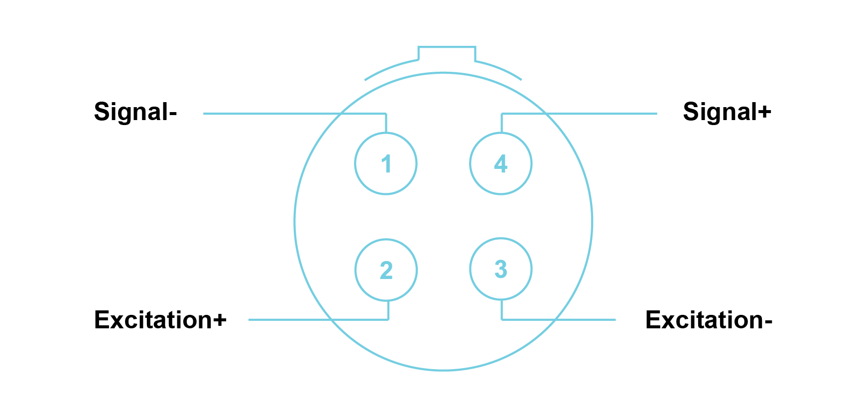 |
ICT42 with male SMB and LEMO® 4-way EHG.0B connectors Module Pin Definition (when looking into the front panel’s connector or at the rear of the cable’s connector)
Features
Please note:The features and specifications may vary based on the software package utilized with the DECAQ
Channels 1 and 2 have the same performance parameters as each channel of the ICP42 Module. Note: Please refer to the ICP42 Module for further details.
ICT42 Specifications
| Tacho Sensor | Voltage (Single-Ended or Differential) |
| Excitation Voltage Level |
Single-Ended Isolated (0 to 12 V) Differential (±12 V) |
| Excitation Maximum Current | 140 mA (fused) |
| Coupling | DC or AC |
| Input Resistance |
Single-Ended 120 kΩ Differential 240 kΩ |
| Over-voltage range | ±60 V |
| Trigger Accuracy | Threshold detection with hysteresis; 16-bit resolution |
| Minimum Pulse Width | 800 ns |
| Scope Mode | 2.048 kHz < fs < 204.8 kHz |
| Module Calibration | Internal amplitude and phase calibration |
| Protection | ESD 2 kV |
| Galvanic Isolation | 50 V |
|
Tacho Trigger Levels Minimum voltage difference between trigger levels |
± 60 V: 2 V ± 30 V: 1 V ± 12 V: 0.5 V ± 2 V: 0.1 V |
ICT42 Specifications
Functionality per Tacho input channel
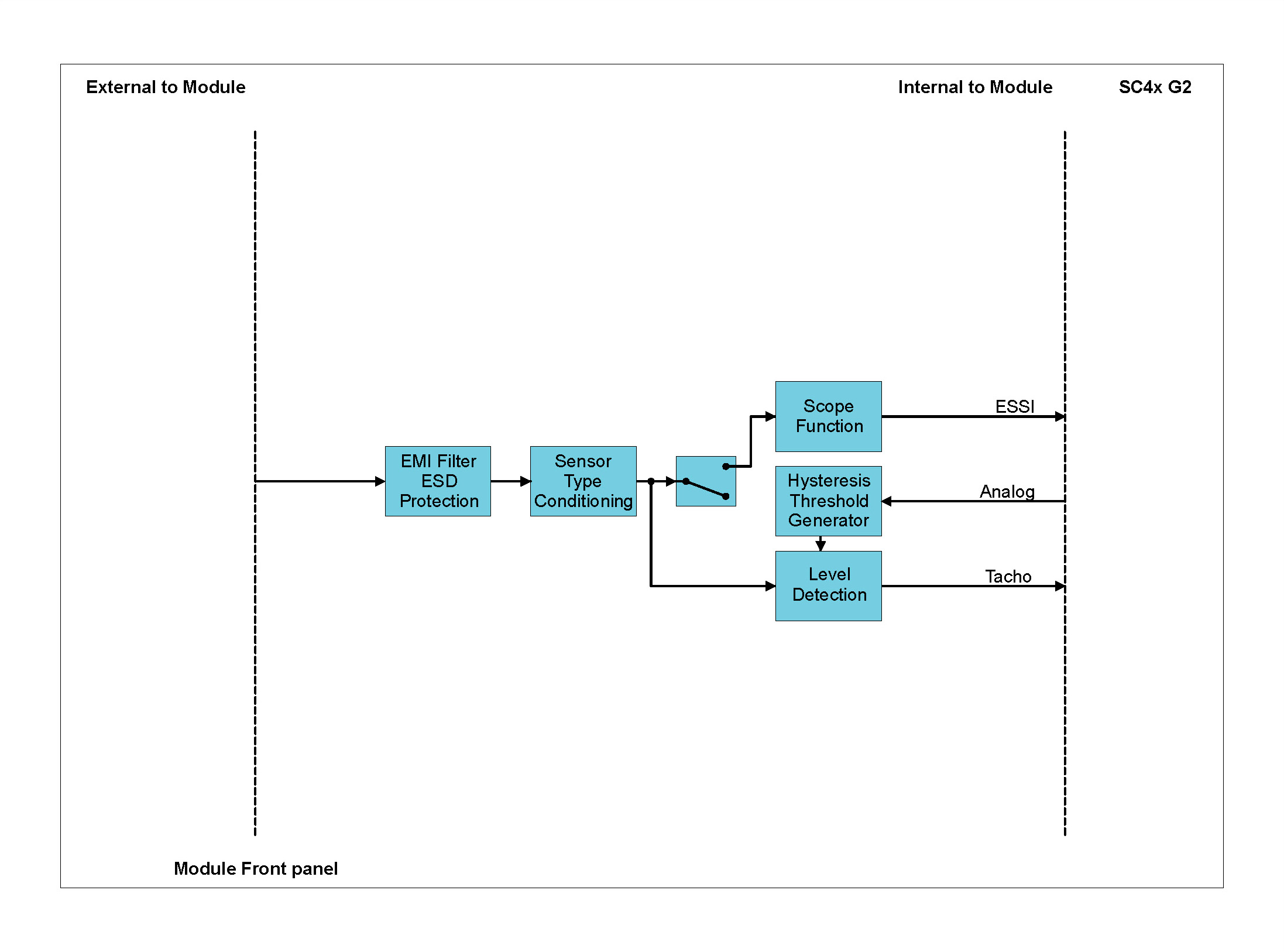
Channels 3 and 4 of the ICT42 Module are both Tacho as well as scope input channels. Each Tacho channel functions separately and is connected to its own Tacho sensor. Each scope channel displays the input of the Tacho channels. The scope channels can be configured to display a single Tacho channel.
As a standard, the ICT42 has a 4-pin LEMO® connector for each Tacho input at the Module front panel. Two of the LEMO® connector pins are for the Tacho signal. The two additional pins provide an excitation voltage that may be used as a power supply to external Tacho sensors. The Excitation+ and Excitation- lines are each protected against a current overload by a 140 mA self-resetting fuse. There are two options for the excitation output as shown in table below.
| Excitation Mode | Description | Diagram |
|---|---|---|
| Differential excitation | The Excitation+ and Excitation- lines are connected to +12 V and -12 V respectively, both positive and negative rails use AGNDM as 0 V reference |  |
| Single-Ended isolated excitation | Excitation+ is connected to +12 V and Excitation- to an isolated ground | 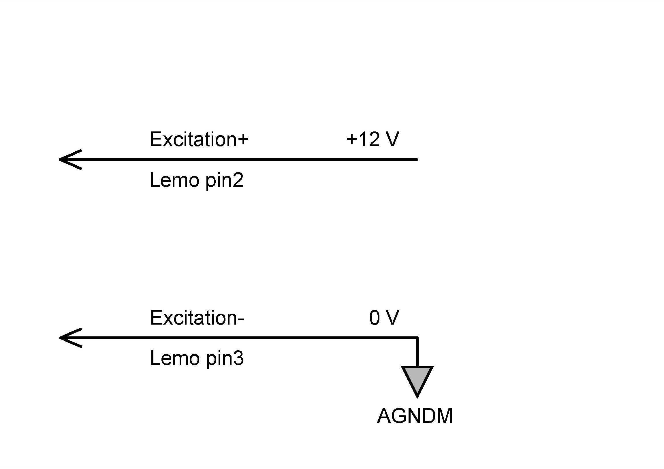 |
ICT42 Excitation description
Grounding options per Tacho input channel
Each Tacho input channel of the ICT42 Module has the following grounding options:
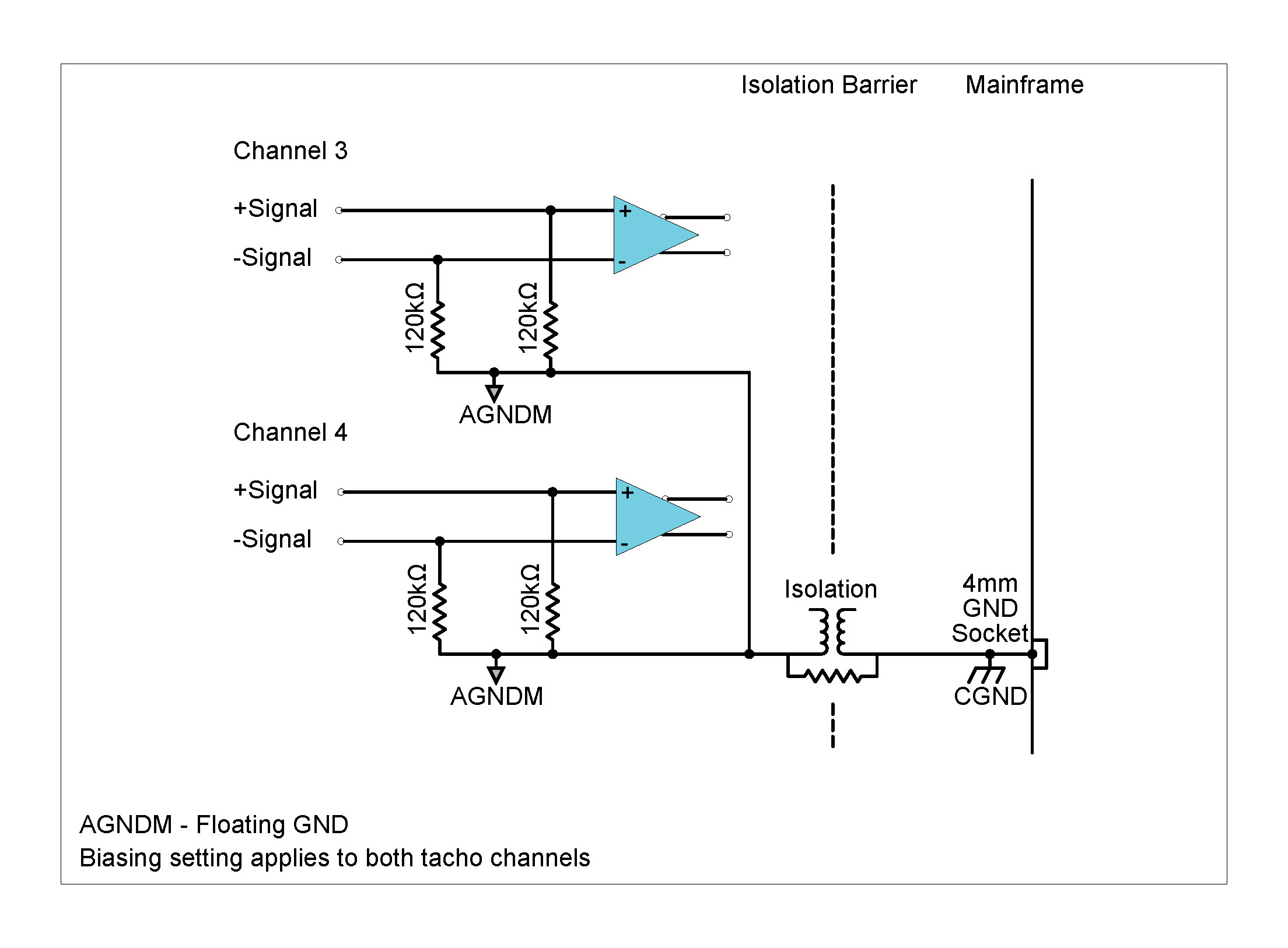

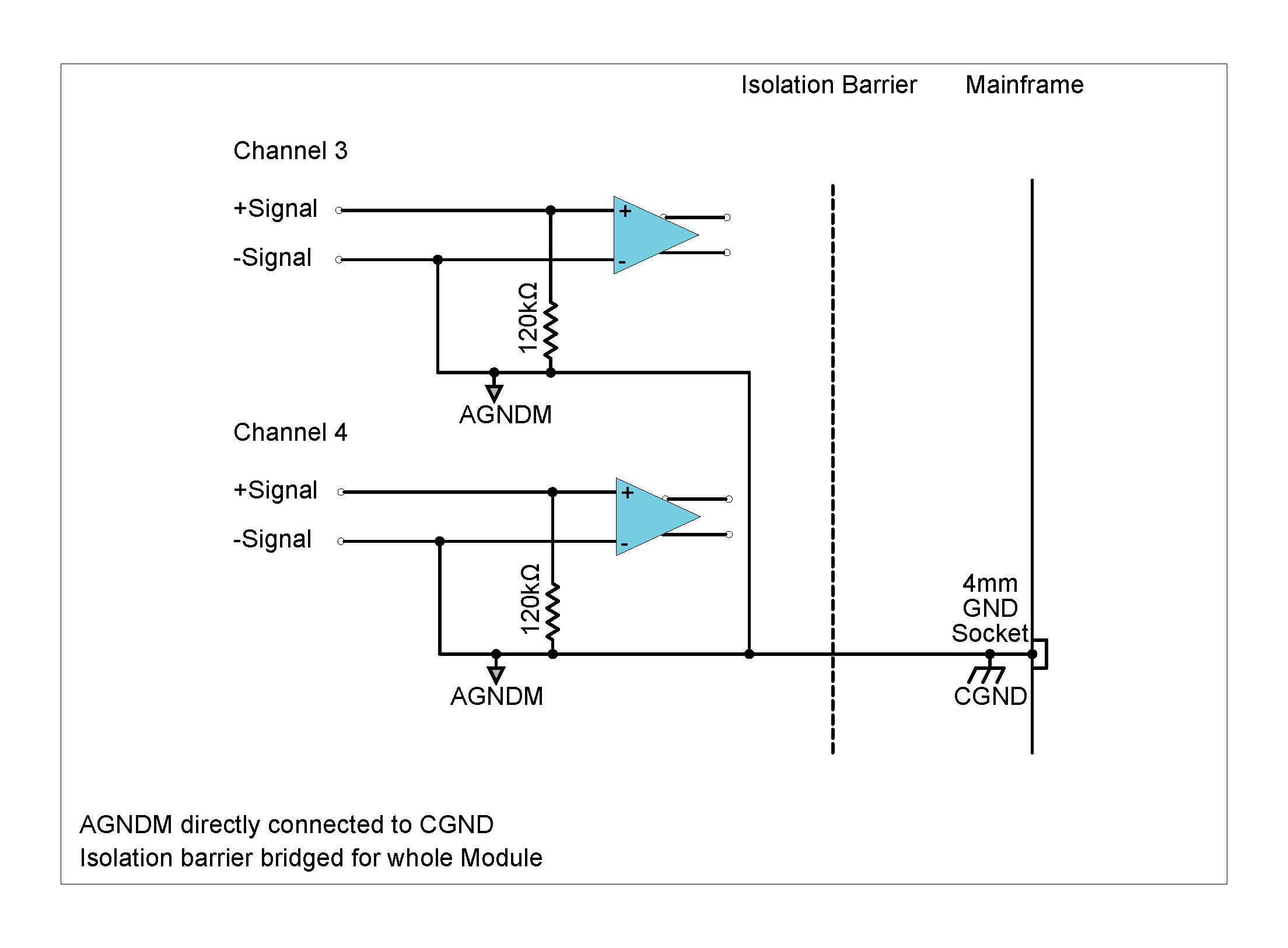
Description
The ICT42S Module is a hybrid Module which combines 2 channels from the advanced ICP42S Module with 2 advanced Tacho input channels. The Tacho channels provide Tacho period measurements with a 20 ns resolution, sampled where the signal intersects its trigger level settings. Triggering of Tacho signals can be set for rising or falling edges with adjustable hysteresis whilst additionally providing AC coupling for sensors with varying DC voltage offsets. A high speed 4.9 MSa/s scope mode is provided to view the Tacho signals in order to assist with the definition of trigger levels. The Module can be used:
| Front Panel | Connector Information and Pin Definitions |
|---|---|
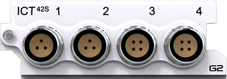 |
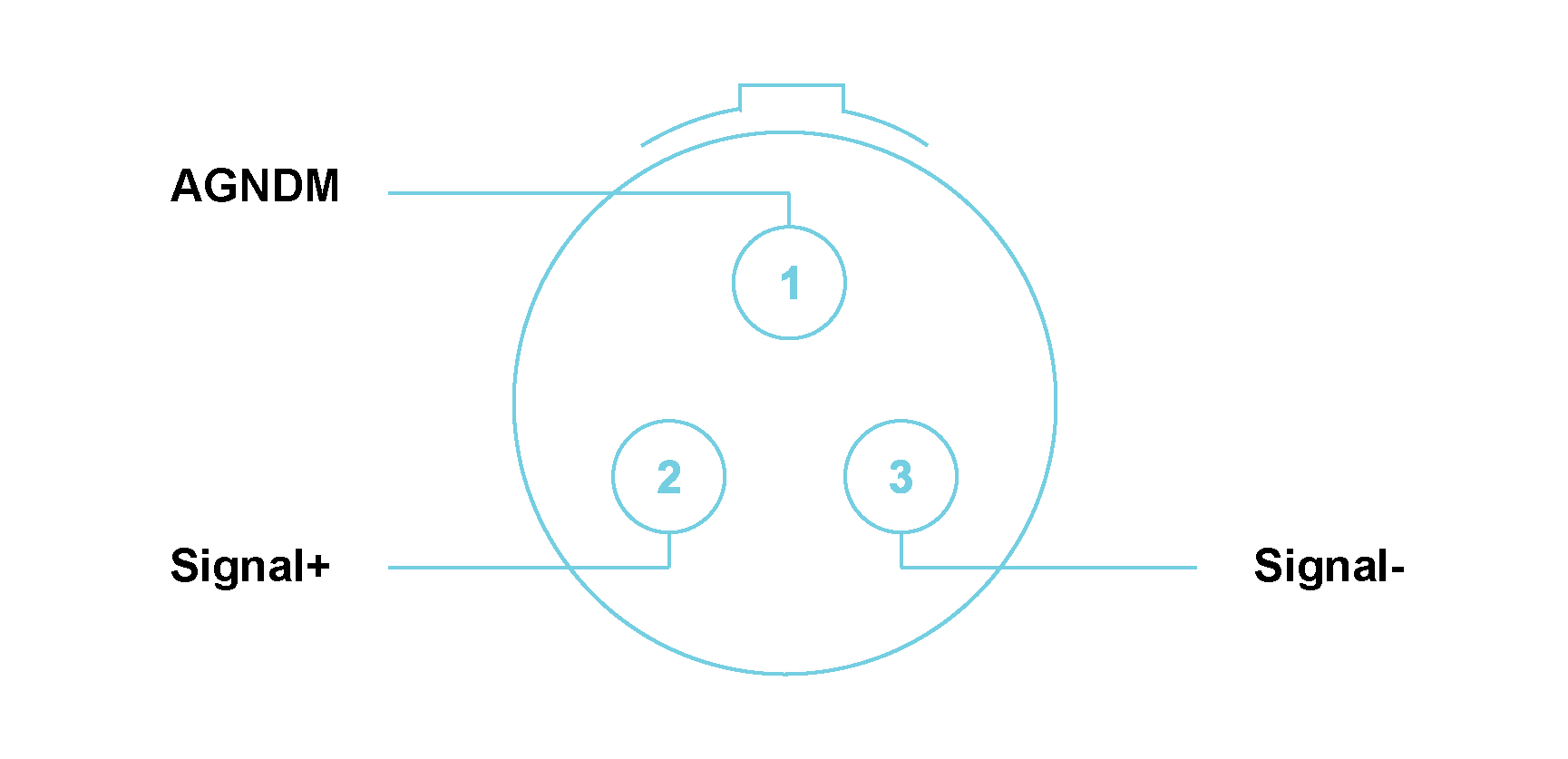 |
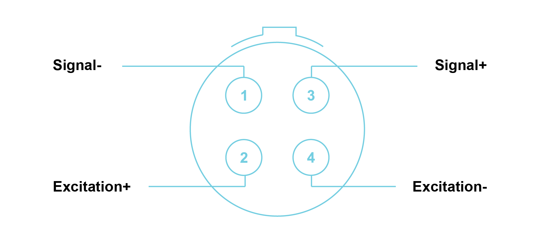 |
ICT42S with LEMO® 3-way and 4-way EHG.0B connectors Module Pin Definition (when looking into the front panel’s connector or at the rear of the cable’s connector)
Features
Please note:The features and specifications may vary based on the software package utilized with the DECAQ
Channels 1 and 2 have the same performance parameters as the first 2 channels of the ICP42S Module. Note: Please see the ICP42S Module for more details about the two ICP® or voltage input mode channels.
ICT42S Specifications
| Tacho Sensor | Voltage (Single-Ended or Differential) |
| Excitation Voltage Level |
Single-Ended Isolated (0 to 12 V) Differential (±12 V) |
| Excitation Maximum Current | 140 mA (fused) |
| Coupling | DC or AC |
| Input Resistance |
Single-Ended 120 kΩ Differential 240 kΩ |
| Over-voltage range | ±60 V |
| Trigger Accuracy | Threshold detection with hysteresis; 16-bit resolution |
| Minimum Pulse Width | 800 ns |
| Scope Mode | 2.048 kHz < fs < 4.9 MHz |
| Module Calibration | Internal amplitude and phase calibration |
| Protection | ESD 2 kV |
| Galvanic Isolation | 50 V |
|
Tacho Trigger Levels Minimum voltage difference between trigger levels |
± 60 V: 2 V ± 30 V: 1 V ± 12 V: 0.5 V ± 2 V: 0.1 V |
ICT42S Specifications
Functionality per Tacho input channel

Channels 3 and 4 of the ICT42S Module are both Tacho as well as scope input channels. Each Tacho channel functions separately and is connected to its own Tacho sensor. Each scope channel displays the input of the Tacho channels. The scope channels can be configured to display a single Tacho channel.
As a standard, the ICT42S has a 4-pin LEMO® connector for each Tacho input at the Module front panel. Two of the LEMO® connector pins are for the Tacho signal. The two additional pins provide an excitation voltage that may be used as a power supply to external Tacho sensors. The excitation+ and excitation- lines are each protected against a current overload by a 140 mA self-resetting fuse. There are two options for the excitation output as shown in table below.
| Excitation Mode | Description | Diagram |
|---|---|---|
| Differential excitation | The Excitation+ and Excitation- lines are connected to +12 V and -12 V respectively, both positive and negative rails use AGNDM as 0 V reference | 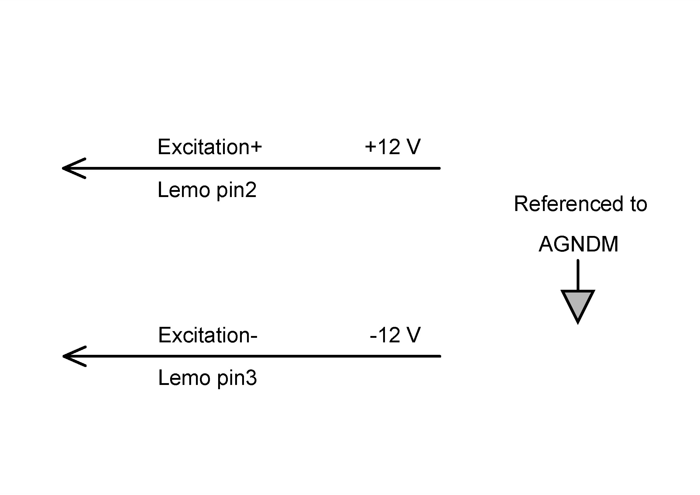 |
| Single-Ended isolated excitation | Excitation+ is connected to +12 V and Excitation- to an isolated ground |  |
Grounding options per Tacho input channel
Each Tacho input channel of the ICT42S Module has the following grounding options:
Grounding diagrams
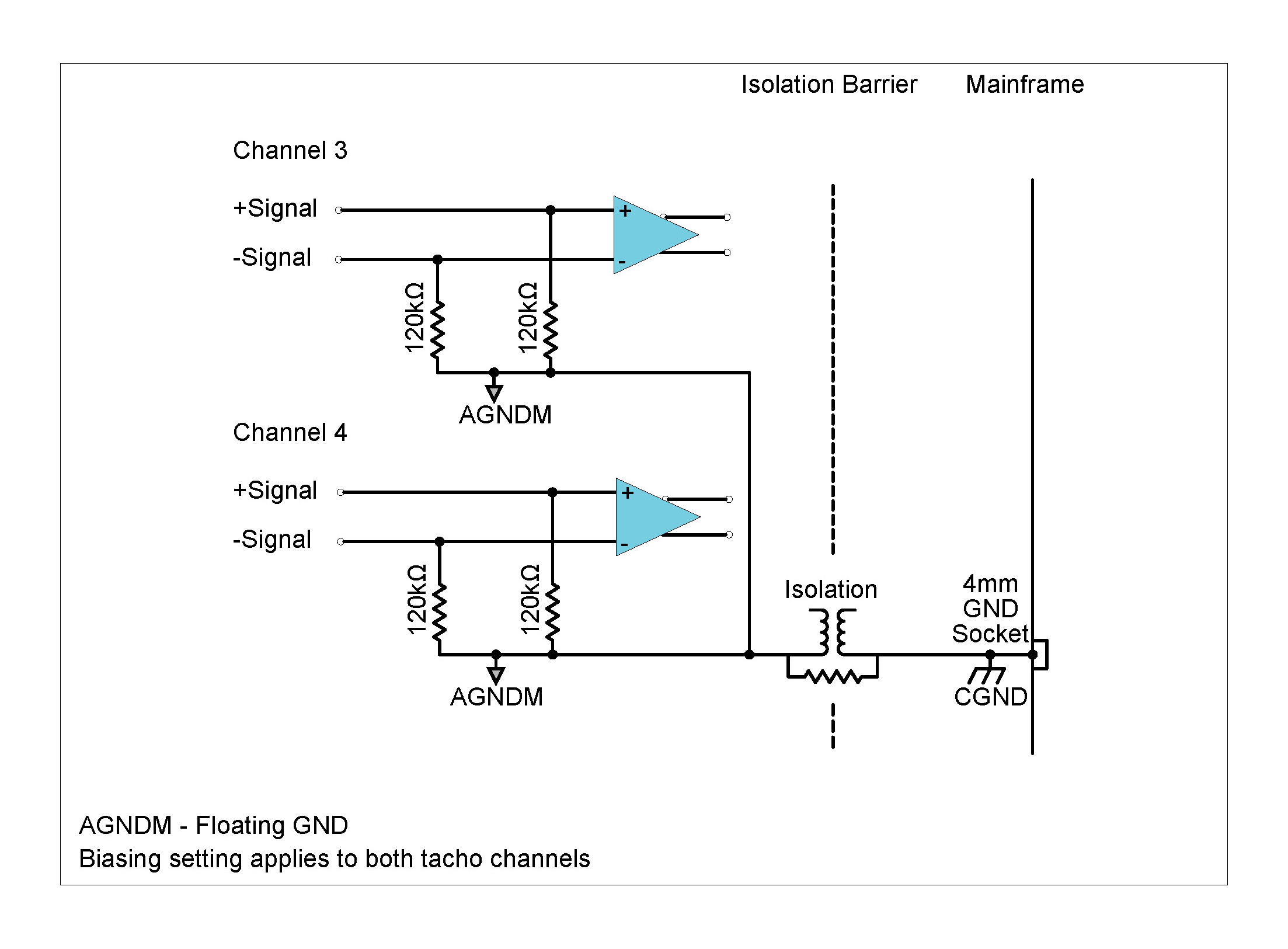
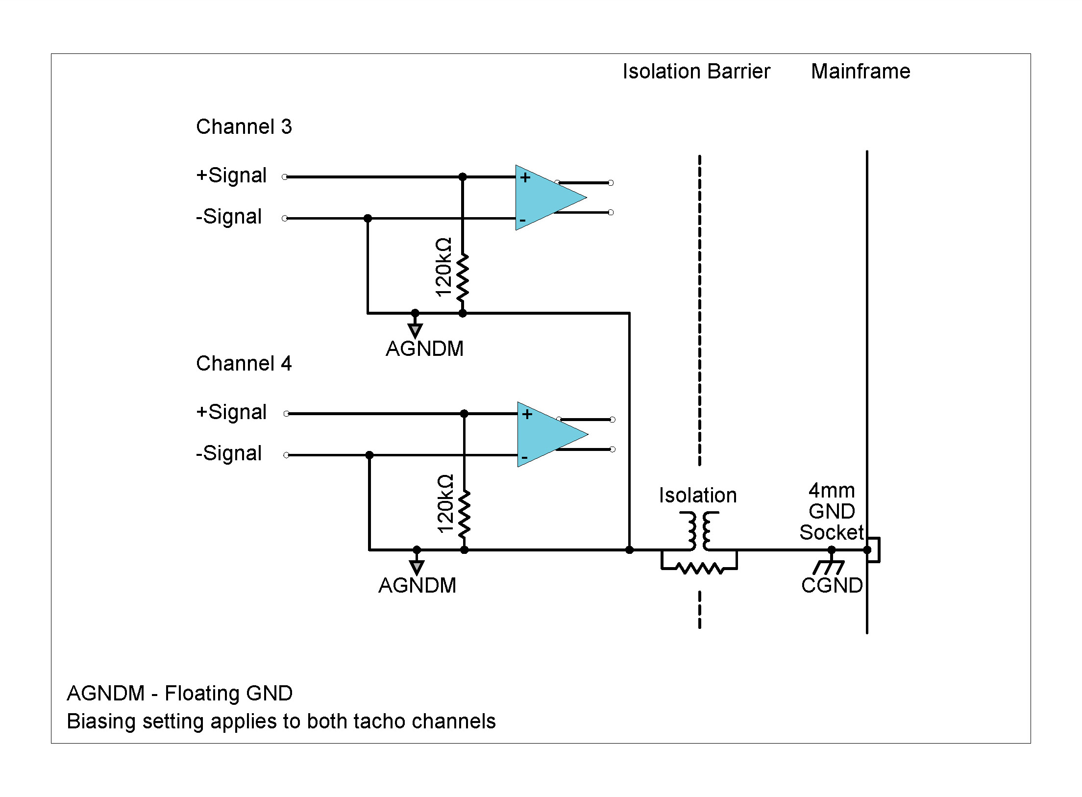
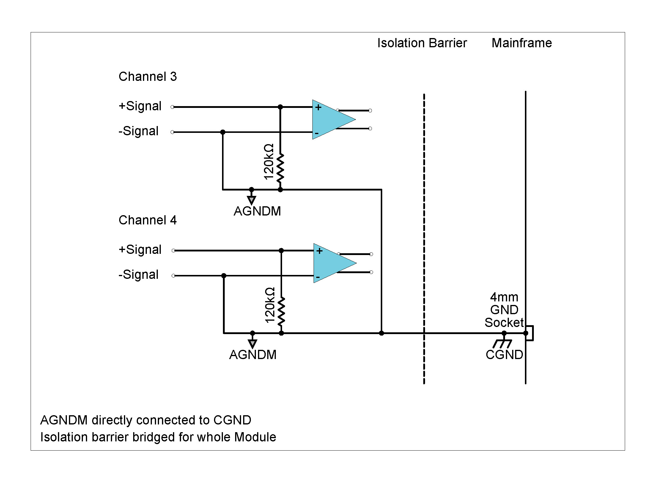
Description
The ICP42 Module can be used with ICP® based accelerometers, force and pressure sensors as well as to measure analog voltages. All 4 channels operate independently of each other, each with their own setting of mode, gain and coupling. The Module can be used with:
| Front Panel | Connector Information and Pin Definitions |
|---|---|
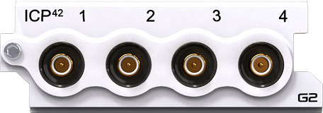 |
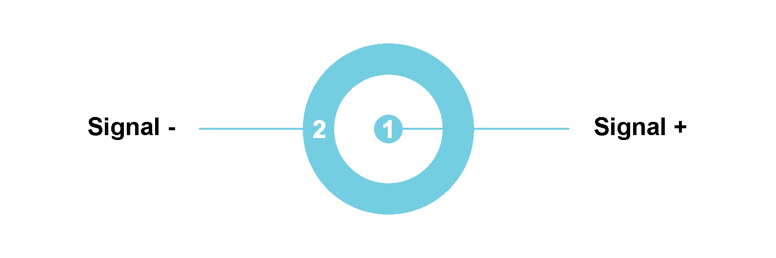 |
ICP42 with male SMB connectors Module Pin Definition (when looking into the front panel’s connector or at the rear of the cable’s connector)
Features
Please note:The features and specifications may vary based on the software package utilized with the DECAQ
ICP42 Specifications
| Interface | ICP® | ICP® sensors | |||
| ALI | For analog source voltages | ||||
| Input Coupling | ICP® | AC | |||
| ALI | DC or AC | ||||
| AC Coupling Frequency Response | ICP® / ALI | Attenuation | Min | Max | Unit |
| -3 dB | - | 0.16 | Hz | ||
| Other Sampling Rates | Available through digital LP filters and decimation | ||||
| Optional Programmable Digital IIR Filter |
Band pass/stop : 6 dB/octave High/Low pass : 12 dB/octave |
||||
| Optional First Order High-Pass Filter | -3 dB @ 1 Hz | ||||
| Module Calibration | Internal amplitude and phase calibration | ||||
| Protection | ICP® / ALI | 2 kV ESD | |||
| ICP® | Short circuit between sensor case and ground | ||||
| Galvanic Isolation | 50 V | ||||
ICP42 Specifications
ICP42 Specifications
| Bandwidth | DC to 49 kHz | ||
| Maximum Sampling Rate (fs) per Channel | 102.4 kSa/s | ||
| A/D Conversion | 24-bit | ||
| Data Transfer | 16/24-bit | ||
| Input Voltage Ranges (Peak) | ±100 mV; ±1 V; ±10 V | ||
| ICP® mode | 4 mA constant current at 24 V excitation | ||
| Input Biasing Settings |
Differential Float (Balanced Float) |
Both the positive and negative signal inputs are connected through 1 MΩ to floating ground | |
|
Single-Ended Float (Unbalanced Float) |
Positive signal input connected through 1 MΩ to floating ground; Negative signal input connected to floating ground | ||
|
Single-Ended GND (Unbalanced GND) |
Positive signal input connected through 1 MΩ to ground; Negative signal input connected to ground | ||
| Input Impedance | Differential | 2 MΩ ‖ 200 pF | |
| Single-Ended | 1 MΩ ‖ 300 pF | ||
|
Digital Low-Pass Filter Filter scales with sampling rate |
Passband | fs x 0.45 Hz | |
| Stopband | fs x 0.55 Hz | ||
| Passband Ripple | ±0.005 dB | ||
| Stopband Attenuation | 100 dB | ||
|
Phase Accuracy Channels in similar range |
Typical1 | < 0.2° at 10 kHz | |
ICP42 Specifications
1 Measured in 10 V range at 102.4 kSa/s
| DC Voltage Accuracy | Input Range (Peak) | Reading + % Range | ||
| ±100 mV | 0.275 % + 0.275 % | |||
| ±1 V | 0.062 % + 0.023 % | |||
| ±10 V | 0.089 % + 0.006 % | |||
|
Noise Input terminated by 50 Ω resistor |
Input Range (Peak) | Guaranteed | Typical | |
| 10 Hz to 23 kHz | ±100 mV | < 3.5 µVrms | < 2.5 µVrms | |
| 10 Hz to 49 kHz | < 4 µVrms | < 3 µVrms | ||
| 10 Hz to 23 kHz | ±1 V | < 10 µVrms | < 7 µVrms | |
| 10 Hz to 49 kHz | < 14 µVrms | < 10 µVrms | ||
| 10 Hz to 23 kHz | ±10 V | < 50 µVrms | < 41 µVrms | |
| 10 Hz to 49 kHz | < 85 µVrms | < 74 µVrms | ||
|
Dynamic Range2 Input terminated by 50 Ω resistor |
Input Range (Peak) | Typical | ||
| ±100 mV | >120 dB | |||
| ±1 V | >130 dB | |||
| ±10 V | >130 dB | |||
|
Amplitude Flatness Relative to 1 kHz Measured up to 0.39 x fs |
Sampling Rate (fs) | Input Range (Peak) | Attenuation (Input signal level 100 % of full range) | |
| 51.2 kSa/s | ±100 mV | − 0.04 dB | ||
| 102.4 kSa/s | − 0.10 dB | |||
| 51.2 kSa/s | ±1 V | − 0.05 dB | ||
| 102.4 kSa/s | − 0.07 dB | |||
| 51.2 kSa/s | ±10 V | − 0.04 dB | ||
| 102.4 kSa/s | − 0.05 dB | |||
| Crosstalk | Input Range (Peak) | Guaranteed | Typical | |
| ±100 mV | 113 dB | 118 dB | ||
| ±1 V | 110 dB | 115 dB | ||
| ±10 V | 102 dB | 107 dB | ||
ICP42 Specifications 2 Dynamic range calculated at sampling rate of 51.2 kSa/s, with a 4096-point FFT.
Specification number: SP150601, Release 3.1. The Module settings and measurement conditions that were used during specification measurements are available on request.
Functionality per Channel
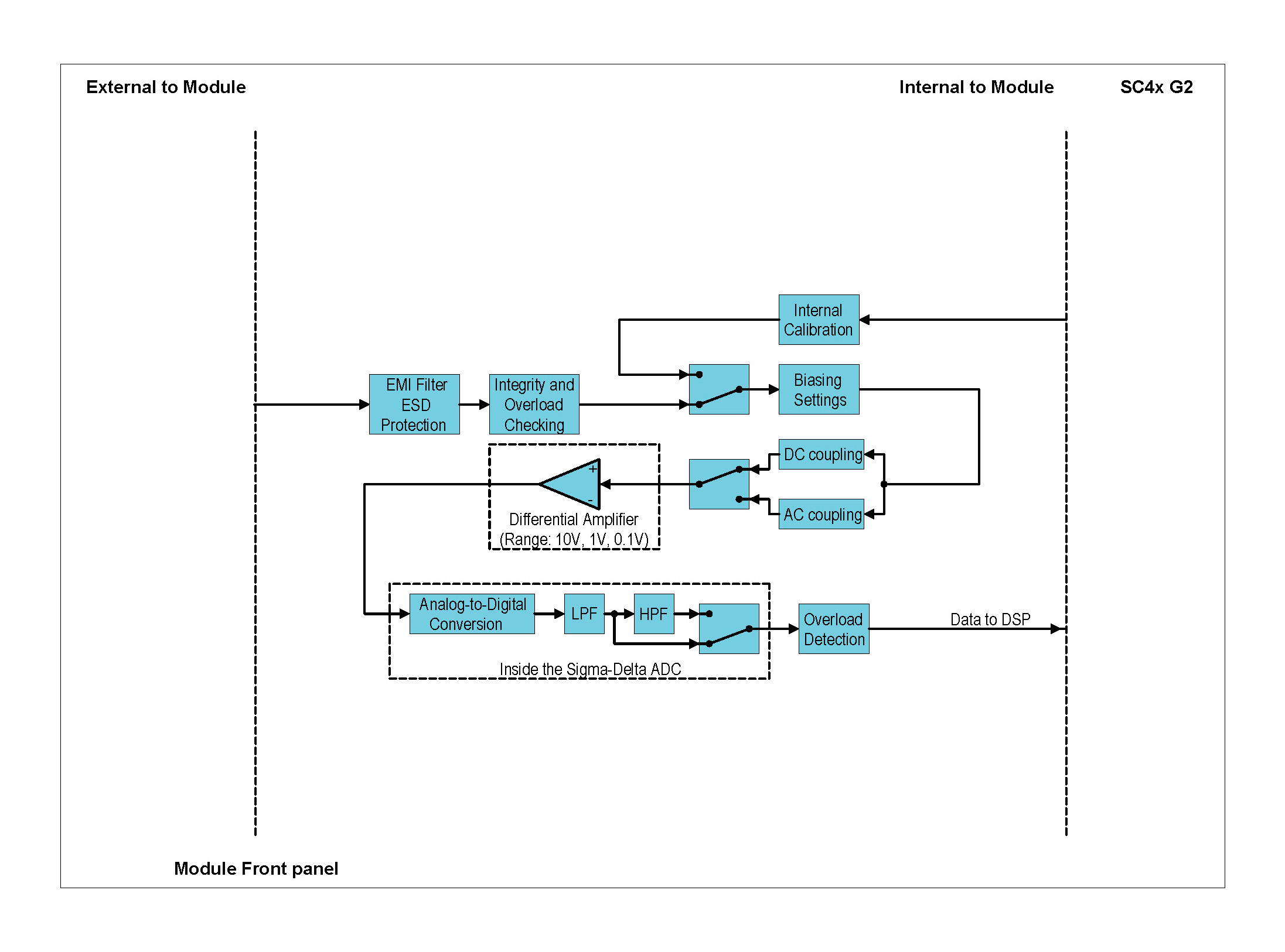

The addition of a 24 V power rail to the ICP42 assures advancement in the overall grounding of the Module:
Grounding Diagrams: ALI mode (Voltage Input mode)

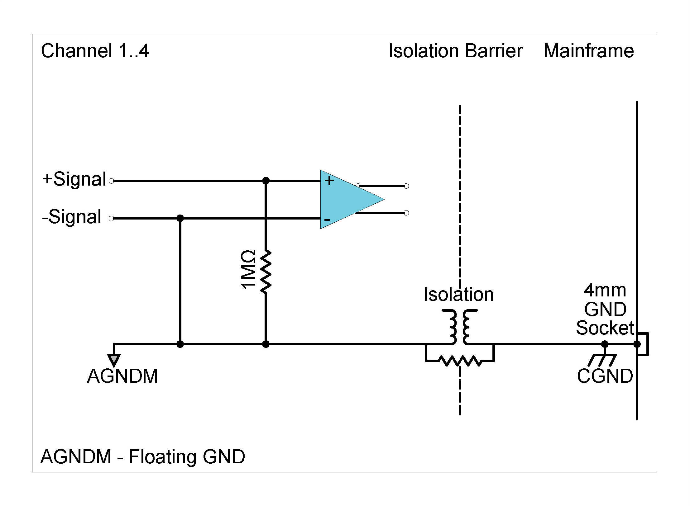

Although each channel in the ICP42 can be set individually as to its grounding type, enabling the single-ended ground option on any one channel will cause all four channels to be connected directly to ground. Software3 will automatically set the grounding type to single-ended ground when one of the channels has been configured in this way.

There are three grounding types when using ICP® input mode:
3These grounding types may vary based on the software package utilized with the DECAQ
Grounding Diagrams: ICP® mode

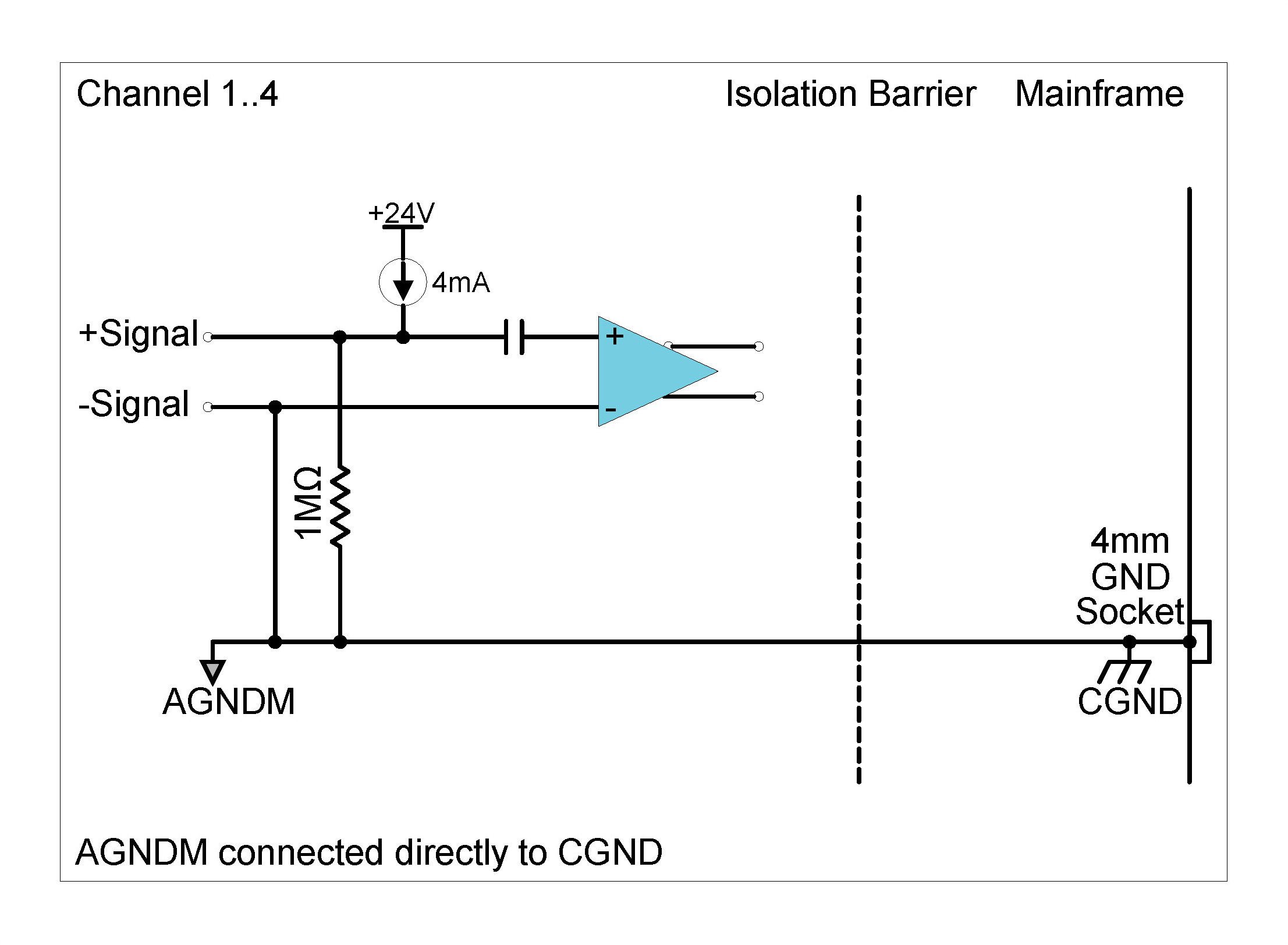
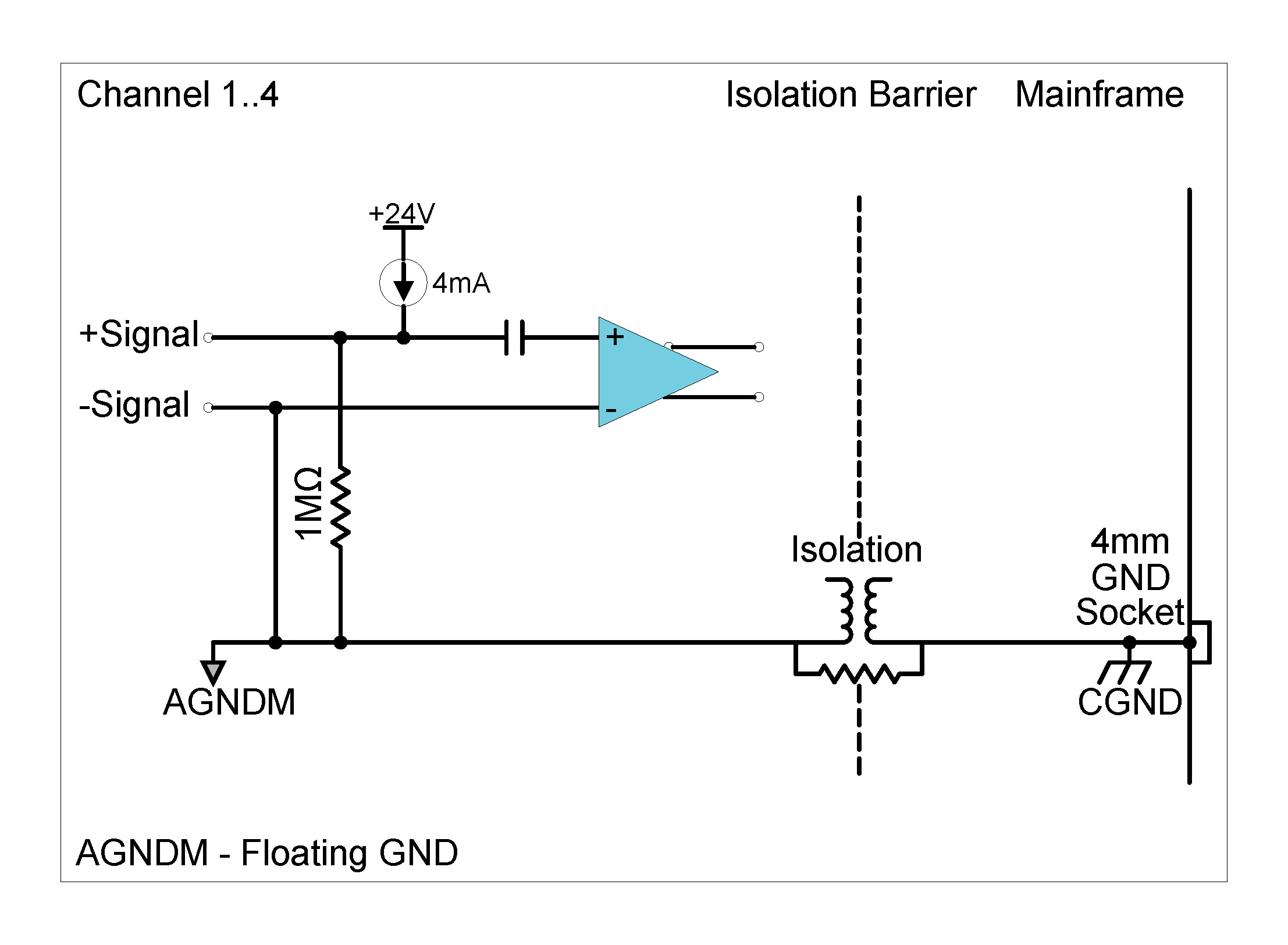
Description
The ICP42S Module can be used with ICP® based accelerometers, force and pressure sensors as well as to measure analog voltages. All 4 channels operate independently of each other, each with their own setting of mode, gain and coupling. The ICP42S furthers the ICP42 by sharing many of the same features and advancing others. The Module can be used with:
| Front Panel | Connector Information and Pin Definitions |
|---|---|
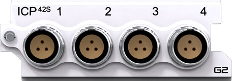 |
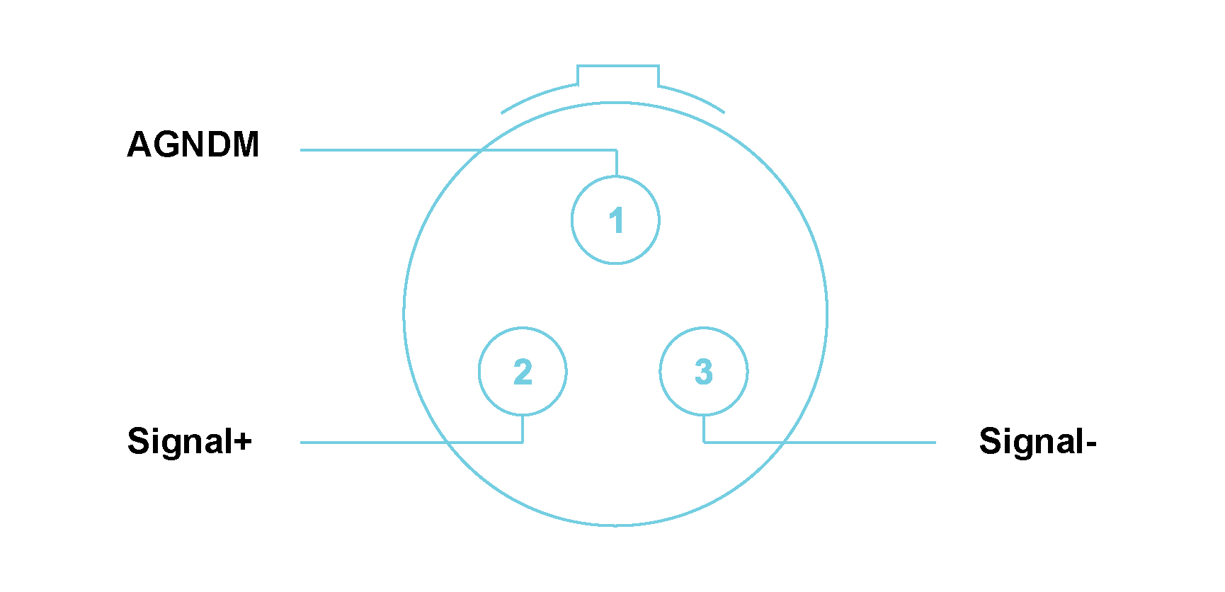 |
ICP42S with LEMO® 3-way EHG.0B connectors Module Pin Definition (when looking into the front panel’s connector or at the rear of the cable’s connector)
Features
Please note:The features and specifications may vary based on the software package utilized with the DECAQ
ICP42S Specifications
| Interface | ICP® | ICP® sensors | |||
| ALI | For analog source voltages | ||||
| Input Coupling | ICP® | AC | |||
| ALI | DC or AC | ||||
| AC Coupling Frequency Response | ICP®/ALI | Attenuation | Min | Max | Unit |
| -3 dB | - | 0.16 | Hz | ||
| Other Sampling Rates | Available through digital LP filters and decimation | ||||
| Optional Programmable Digital IIR Filter | Band pass/stop: 6 dB/octave | ||||
| High/Low pass: 12 dB/octave | |||||
| Optional First Order High-Pass Filter | -3 dB @ 1 Hz | ||||
| Module Calibration | Internal amplitude and phase calibration | ||||
| Protection | ICP®/ALI | 2 kV ESD | |||
| ICP® | Short circuit between sensor case and ground | ||||
| Galvanic Isolation | 50 V | ||||
ICP42S Specifications
ICP42S User Manual Specifications
| Bandwidth | DC to 100 kHz | ||
| Maximum Sampling Rate (fs) per Channel | 204.8 kSa/s | ||
| A/D Conversion | 24-bit | ||
| Data Transfer | 16/24-bit | ||
| Input Voltage Ranges (Peak) | ±100 mV; ±1 V; ±10 V; ±60 V | ||
| ICP® Mode | 4 mA; 8 mA or 12 mA constant current at 24 V excitation | ||
| Input Biasing Settings |
Differential Float (Balanced Float) |
Both the positive and negative signal inputs are connected through 1 MΩ to floating ground | |
|
Single-Ended Float (Unbalanced Float) |
Positive signal input connected through 1 MΩ to floating ground; Negative signal input connected to floating ground | ||
|
Single-Ended GND (Unbalanced GND) |
Positive signal input connected through 1 MΩ to ground; Negative signal input connected to ground | ||
| Input Impedance | Differential | 2 MΩ ‖ 200 pF | |
| Single-Ended | 1 MΩ ‖ 300 pF | ||
|
Digital Low-Pass Filter Filter scales with sampling rate |
Passband | fs x 0.45 Hz | |
| Stopband | fs x 0.55 Hz | ||
| Passband Ripple | ±0.005 dB | ||
| Stopband Attenuation | 100 dB | ||
|
Phase Accuracy Channels in similar range |
|
< 0.2° at 10 kHz | |
ICP42S Specifications
1 Measured in 10 V range at 204.8 kSa/s
| DC Voltage Accuracy | Input Range (Peak) | % Reading + % Range | ||
| ±100 mV | 0.275 % + 0.275 % | |||
| ±1 V | 0.068 % + 0.023 % | |||
| ±10 V | 0.089 % + 0.006 % | |||
| ± 60 V | 1.187 % + 0.013 % | |||
|
Noise Input terminated by 50 Ω resistor |
Input Range (Peak) | Guaranteed | Typical | |
| 10 Hz to 23 kHz | ±100 mV | < 3.5 µVrms | < 2.5 µVrms | |
| 10 Hz to 49 kHz | < 4 µVrms | < 3 µVrms | ||
| 10 Hz to 100 kHz | < 12 µVrms | < 10 µVrms | ||
| 10 Hz to 23 kHz | 1 V | < 10 µVrms | < 7 µVrms | |
| 10 Hz to 49 kHz | < 14 µVrms | < 10 µVrms | ||
| 10 Hz to 100 kHz | < 90 µVrms | < 85 µVrms | ||
| 10 Hz to 23 kHz | ±10 V | < 50 µVrms | < 41 µVrms | |
| 10 Hz to 49 kHz | < 85 µVrms | < 74 µVrms | ||
| 10 Hz to 100 kHz | < 870 µVrms | < 840 µVrms | ||
| 10 Hz to 23 kHz | ±60 V | < 580 µVrms | < 470 µVrms | |
| 10 Hz to 49 kHz | < 780 µVrms | < 660 µVrms | ||
| 10 Hz to 100 kHz | < 4500 µVrms | < 4300 µVrms | ||
|
Dynamic Range2 Input terminated by 50 Ω resistor |
Input Range (Peak) | Typical | ||
| ±100 mV | > 130 dB | |||
| ±1 V | > 130 dB | |||
| ±10 V | > 130 dB | |||
| ± 60 V | > 130 dB | |||
|
Amplitude Flatness Relative to 1 kHz Measured up to 0.39 x fs |
Sampling Rate (fs) | Input Range (Peak) | Attenuation (Input signal level 100 % of full range) | |
| 51.2 kSa/s | ±100 mV | − 0.04 dB | ||
| 102.4 kSa/s | − 0.10 dB | |||
| 204.8 kSa/s | − 0.32 dB | |||
| 51.2 kSa/s | ±1 V | − 0.05 dB | ||
| 102.4 kSa/s | − 0.07 dB | |||
| 204.8 kSa/s | − 0.18 dB | |||
| 51.2 kSa/s | ±10 V | − 0.04 dB | ||
| 102.4 kSa/s | − 0.05 dB | |||
| 204.8 kSa/s | − 0.10 dB | |||
| 51.2 kSa/s | ±60 V | − 0.05 dB | ||
| 102.4 kSa/s | − 0.09 dB | |||
| 204.8 kSa/s | − 0.26 dB | |||
| Crosstalk | Input Range (Peak) | Guaranteed | Typical | |
| ±100 mV | 113 dB | 118 dB | ||
| ±1 V | 110 dB | 115 dB | ||
| ±10 V | 102 dB | 107 dB | ||
| ±60 V | 84 dB | 89 dB | ||
ICP42S Specifications 2 Dynamic range calculated at sampling rate of 51.2 kSa/s, with a 4096-point FFT.
Specification number: SP150600, Release 3.1. The Module settings and measurement conditions that were used during specification measurements are available on request.
Functionality per Channel
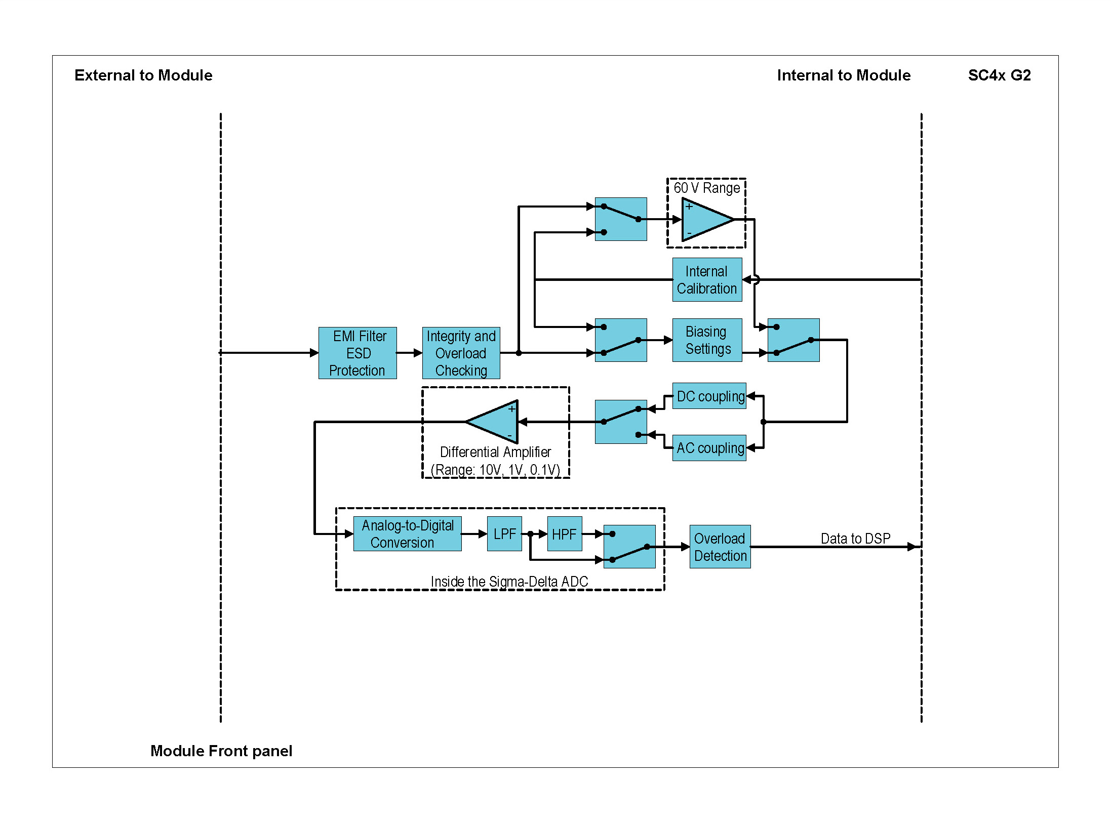
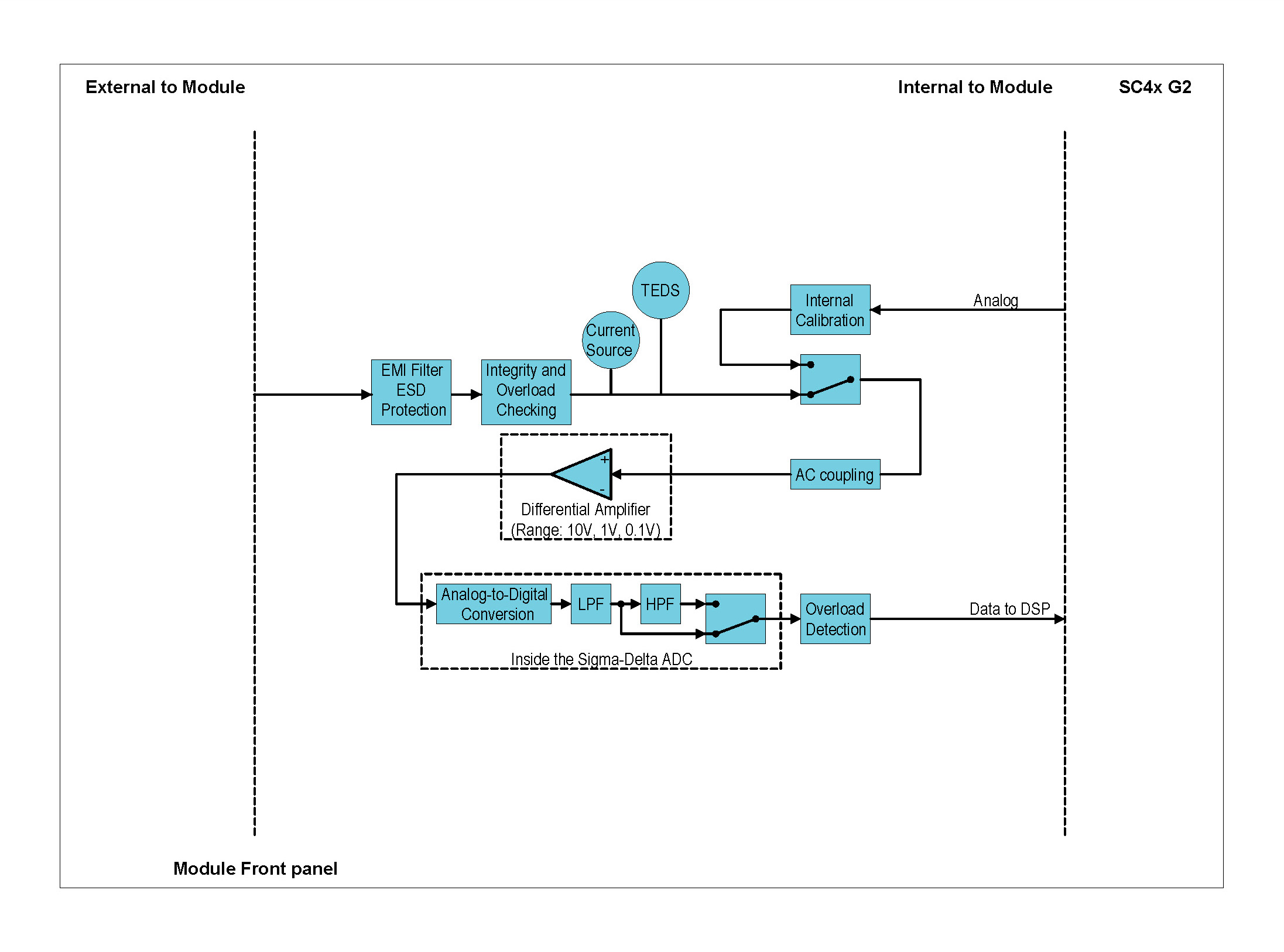
Grounding options
The addition of a 24 V power rail to the ICP42S assures advancement in the overall grounding of the Module:
Grounding Diagrams: ALI mode (Voltage Input mode)
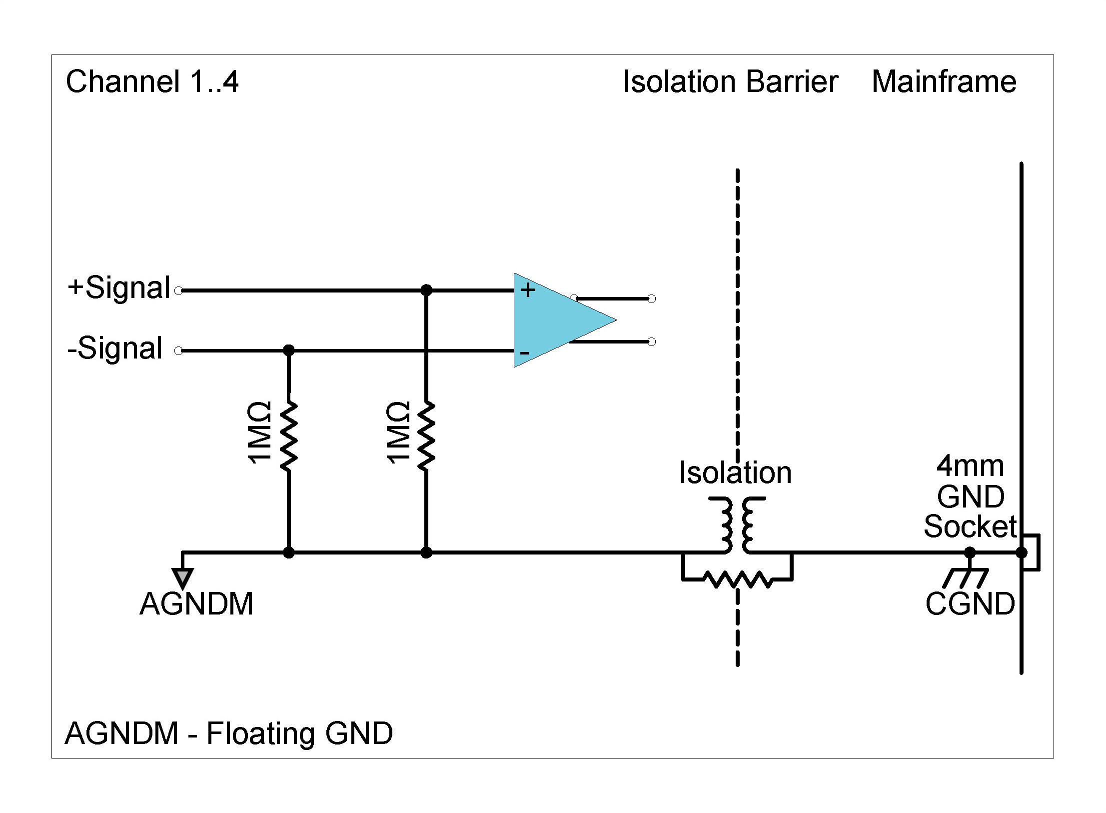

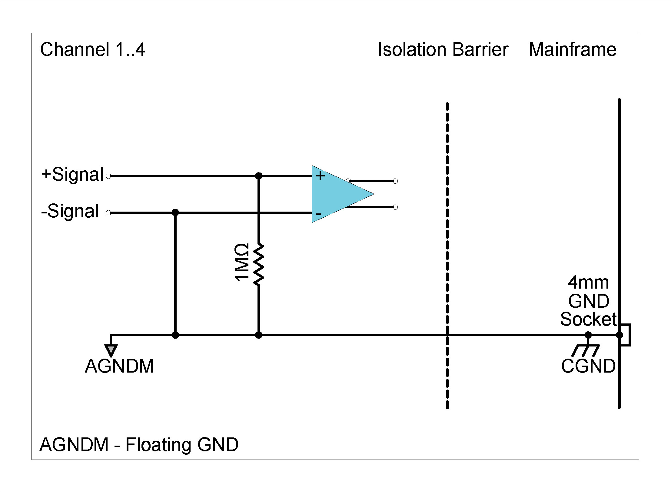
Although each channel in the ICP42S can be set individually as to its grounding type, enabling the single-ended ground option on any one channel will cause all four channels to be connected directly to ground. Software will automatically set the grounding type to single-ended ground when one of the channels has been configured in this way.
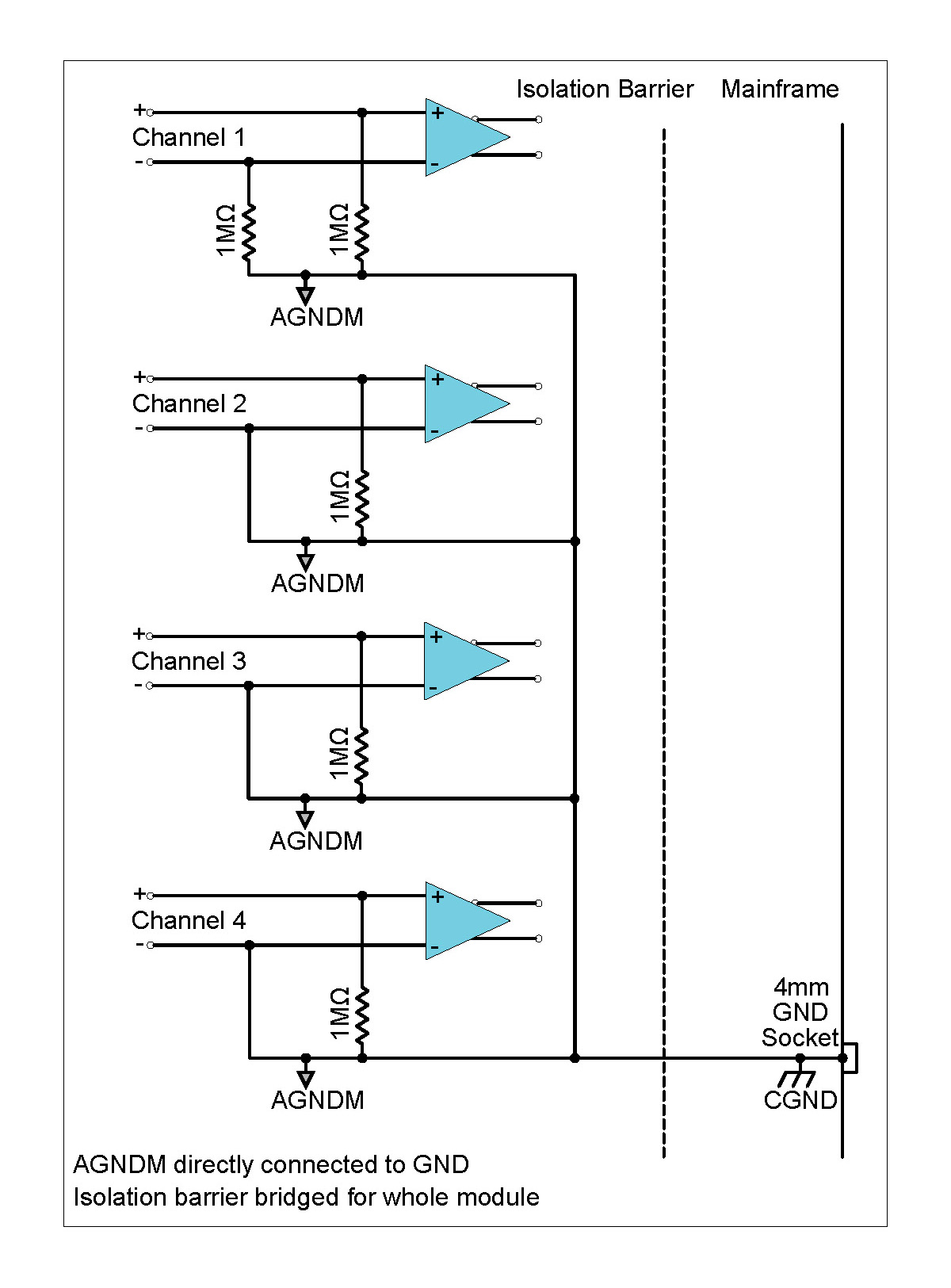
Similar to the ALI mode there are again three grounding types in ICP® input mode. With ICP® Input mode there is another configuration option, namely the amount of current excitation which can be provided to an attached sensor.
Grounding Diagrams: ICP® mode
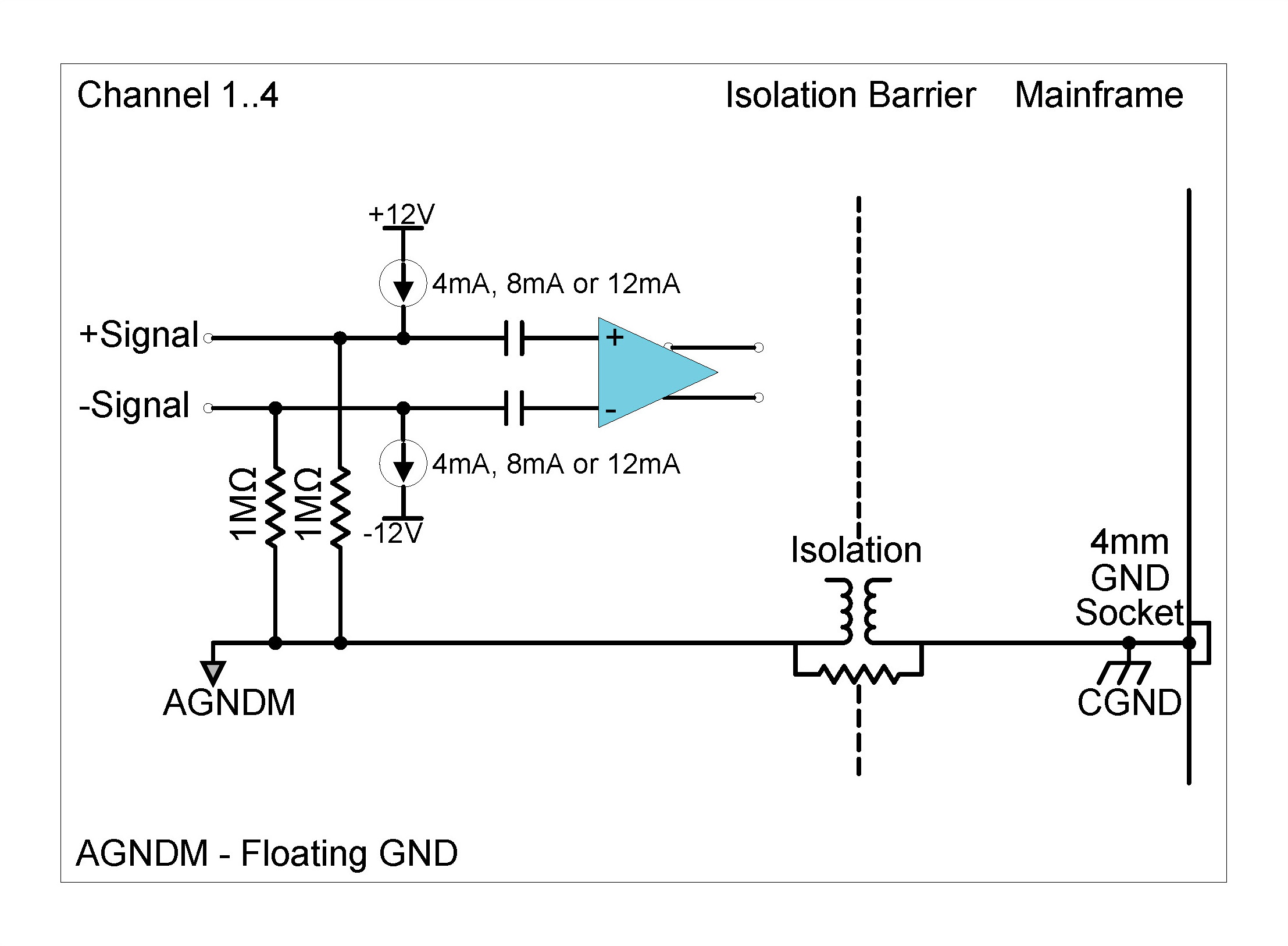

Description
The WSB42X Module is used with AC and DC bridge measurements including strain gauges configured as full, half or quarter bridges and inductive displacement transducers (LVDT). The Module offers numerous software selectable features such as constant voltage (AC or DC) and constant current excitation (DC), bridge sensing, bridge completion resistors, shunt calibration, dynamic strain mode and ICP® sensor support. The bridge can be balanced on command or a previous balance value can be recalled. The Module can be used with:
| Front Panel | Connector Information and Pin Definitions |
|---|---|
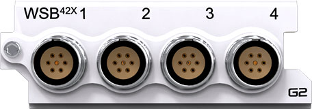 |
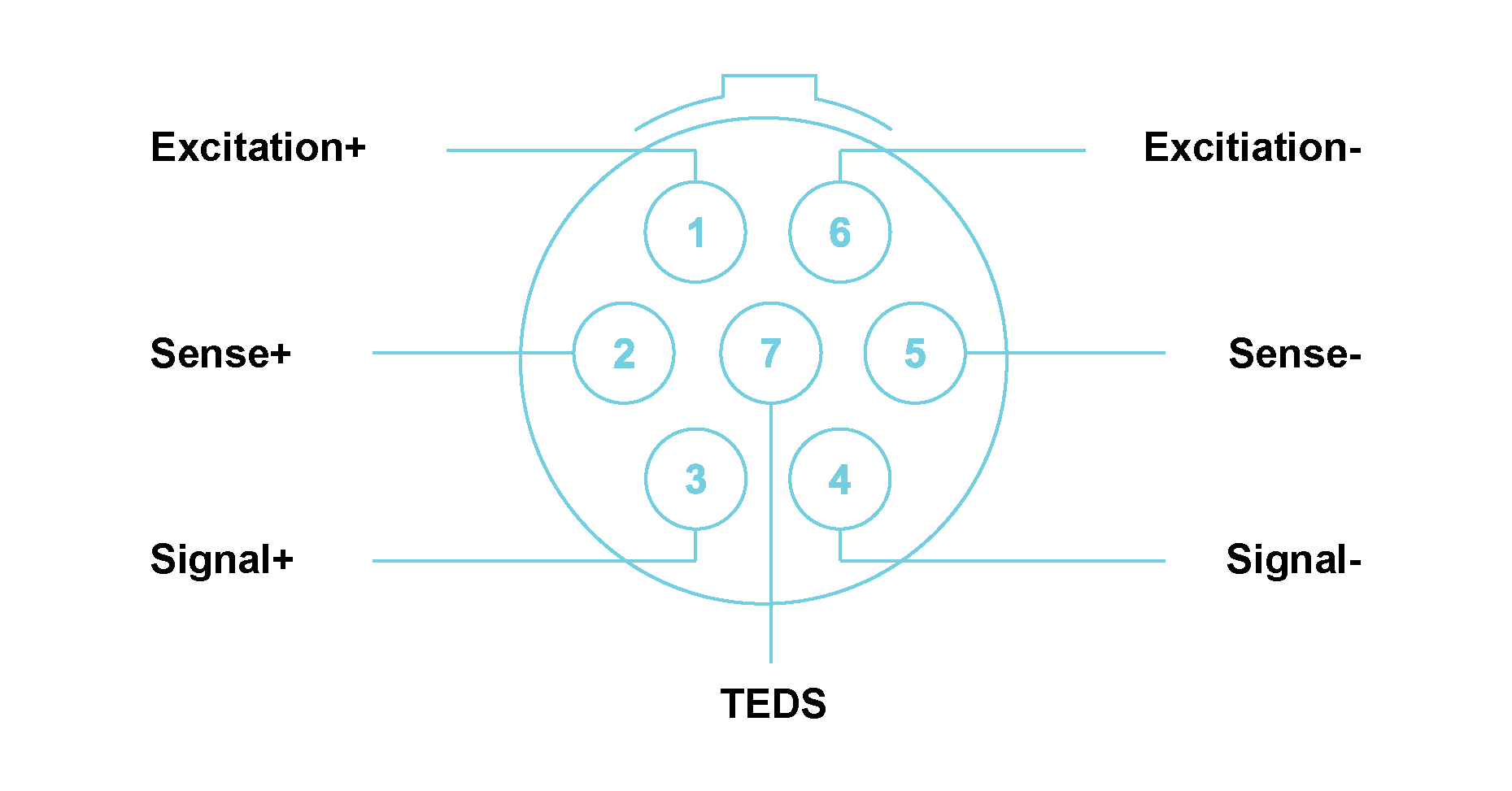 |
WSB42X with LEMO® 7-way EHG.0B connectors Module Pin Definition (when looking into the front panel’s connector or at the rear of the cable’s connector)
Features
Please note:The features and specifications may vary based on the software package utilized with the DECAQ
WSB42X Specifications
| Bridge Type | Resistive or inductive | ||||
| Interface | ICP® | ICP® sensors | |||
| ALI | For analog voltage sources | WSB | Wheatstone bridge sensors | ||
| Interface | ICP® | AC | |||
| ALI / WSB | DC or AC | ||||
| AC Coupling Frequency Response | ICP® / ALI / WSB | Attenuation | Min | Max | Unit |
| -3 dB | - | 1.5 | Hz | ||
WSB42X Specifications
|
Bridge Balancing Ranges for Voltage Excitation Represents minimum or maximum resistance of a single element if other three bridge elements remain at their nominal value |
Bridge Resistance | Excitation Voltage | Minimum Resistance | Maximum Resistance | |
| 120 Ω | 0.5 - 5 V | 0 Ω | Unlimited | ||
| 5.5 V | 6 Ω | 2520 Ω | |||
| 6 V | 11 Ω | 1320 Ω | |||
| 350 Ω | 0.5 - 5 V | 0 Ω | Unlimited | ||
| 5.5 V | 17 Ω | 7350 Ω | |||
| 6 V | 32 Ω | 3850 Ω | |||
| 1 kΩ | 8.5 V | 850 Ω | 3850 Ω | ||
| 9 V | 850 Ω | 3500 Ω | |||
| 9.5 V | 850 Ω | 3220 Ω | |||
| 10 V | 850 Ω | 3000 Ω | |||
|
Bridge Balancing Ranges for Current Excitation Represents minimum or maximum resistance of a single element if other three bridge elements remain at their nominal value |
Bridge Resistance | Excitation Current | Minimum Resistance (2-wire and 4-wire) | Maximum Resistance (2-wire) | Maximum Resistance (4-wire) |
| 120 Ω | 4 mA | 0 Ω | Unlimited | Unlimited | |
| 8 mA | 0 Ω | Unlimited | Unlimited | ||
| 12 mA | 0 Ω | Unlimited | Unlimited | ||
| 350 Ω | 4 mA | 0 Ω | Unlimited | Unlimited | |
| 8 mA | 0 Ω | 12000 Ω | 12000 Ω | ||
| 12 mA | 0 Ω | 2400 Ω | 2400 Ω | ||
| 1 kΩ | 4 mA | 0 Ω | 7660 Ω | 7660 Ω | |
| 8 mA | 48 Ω | 2810 Ω | 2810 Ω | ||
| 12 mA | 310 Ω | 2050 Ω | 1360 Ω | ||
|
Constant Current Excitation 2-Wire Signal± carries both signal and excitation AC coupled No current monitoring |
Excitation Current | Voltage Compliance | Maximum Sensor Resistance | ||
| 4 mA | 20 V | 5000 Ω | |||
| 8 mA | 20 V | 2500 Ω | |||
| 12 mA | 20 V | 1660 Ω | |||
|
Constant Current Excitation 4-Wire Signal± carries both signal and Excitation± carries excitation AC or DC coupled Current monitoring across ultra-precision resistor |
.
4 mA | 13 V | 3250 Ω | ||
| 8 mA | 13 V | 1620 Ω | |||
| 12 mA | 13 V | 1080 Ω | |||
|
Constant Voltage Excitation |
Excitation Voltage | Maximum Load Current | Voltage Resolution | Polarity | |
| < 6 V | < 90 mA | 0.2 mV | Bipolar (Balanced) | ||
| < 8 to 10 V | < 12 mA | 0.1 mV | Unipolar (Unbalanced) | ||
|
Other Sampling Rates |
Available through digital LP filters and decimation | ||||
|
Optional Programmable Digital IIR Filter |
Band pass/stop : 6 dB/octave | ||||
| High/Low pass : 12 dB/octave | |||||
|
Optional First Order High-Pass Filter |
-3 dB @ 1 Hz | ||||
| Protection | ICP® / ALI / WSB | 2 kV ESD on all lines | |||
| Overvoltage on signal lines | |||||
| ICP® | Short circuit between sensor case and ground | ||||
| WSB | Short circuit between excitation lines | ||||
|
Galvanic Isolation |
50 V | ||||
WSB42X Specifications
WSB42X (All builds preceding Build R) Specifications continue
| Bandwidth | DC to 100 kHz | |||
| Maximum Sampling Rate (fs) per Channel | 204.8 kSa/s | |||
| A/D Conversion | 24-bit | |||
| Data Transfer | 16/24-bit | |||
| Input Voltage Ranges (Peak) | ±10 mV; ±100 mV; ±1 V; ±10 V | |||
| ICP® Mode | 4 mA; 8 mA or 12 mA constant current at ±12 V excitation | |||
| Input Biasing Settings | Differential Float (Balanced Float) | Both the positive and negative signal inputs are connected through 1 MΩ to floating ground | ||
| Input Impedance | 2.1 MΩ ‖ 1200 pF | |||
|
Shunt Calibration Resistor Between Signal- and Excitation+ / Sense+ |
Resistance | Tolerance | Temperature Drift | |
| 100 kΩ | 0.1 % | 5 ppm/°C | ||
| Internal Bridge Completion Resistors | Resistance | Tolerance | Temperature Drift | |
| 120 Ω or 350 Ω | 0.02 % | 0.2 ppm/°C | ||
|
Digital Low-Pass Filter Filter scales with sampling rate |
Passband | fs x 0.45 Hz | ||
| Stopband | fs x 0.55 Hz | |||
| Passband Ripple | ±0.005 dB | |||
| Stopband Attenuation | 100 dB | |||
|
Phase Accuracy Channels in similar range |
Typical1 | < 0.2° at 10 kHz | ||
| Wheatstone Bridge Current-Excitation | Excitation Mode | % Excitation Mode + mA | ||
| 2-wire | 4 mA | 0.58 % + 0.025 mA | ||
| 8 mA | 0.38 % + 0.031 mA | |||
| 12 mA | 0.36 % + 0.042 mA | |||
| 4-wire | 4 mA | 0.58 % + 0.011 mA | ||
| 8 mA | 0.38 % + 0.018 mA | |||
| 12 mA | 0.36 % + 0.029 mA | |||
| Wheatstone Bridge Voltage-Excitation | Excitation Voltage | Maximum Error Voltage | ||
| < 6 V | ± 4 mV | |||
| 8 to 10 V | ± 4 mV | |||
| DC Voltage Accuracy | Input Range (Peak) | % Reading + % Range | ||
| ±10 mV | To be determined | |||
| ±100 mV | 0.12 % + 0.18 % | |||
| ±1 V | 0.08 % + 0.07 % | |||
| ±10 V | 0.08 % + 0.07 % | |||
|
Noise Input terminated by 50 Ω resistor |
Input Range (Peak) | Guaranteed | Typical | |
| 10 Hz to 23 kHz | ±10 mV | < 3.6 µVrms | < 2.9 µVrms | |
| 10 Hz to 49 kHz | < 5.8 µVrms | < 4.3 µVrms | ||
| 10 Hz to 100 kHz | < 6.9 µVrms | < 5.6 µVrms | ||
| 10 Hz to 23 kHz | ±100 mV | < 5.0 µVrms | < 4.4 µVrms | |
| 10 Hz to 49 kHz | < 10 µVrms | < 7.8 µVrms | ||
| 10 Hz to 100 kHz | < 82 µVrms | < 72 µVrms | ||
| 10 Hz to 23 kHz | ±1 V | < 5 µVrms | < 4.4 µVrms | |
| 10 Hz to 49 kHz | < 10 µVrms | < 7.8 µVrms | ||
| 10 Hz to 100 kHz | < 86 µVrms | < 74 µVrms | ||
| 10 Hz to 23 kHz | ±10 V | < 41 µVrms | < 37 µVrms | |
| 10 Hz to 49 kHz | < 86 µVrms | < 68 µVrms | ||
| 10 Hz to 100 kHz | < 755 µVrms | < 700 µVrms | ||
|
Dynamic Range2 Input terminated by 50 Ω resistor |
Input Range (Peak) | Typical | ||
| ±10 mV | > 80 dB | |||
| ±100 mV | > 100 dB | |||
| ±1 V | > 110 dB | |||
| ±10 V | > 130 dB | |||
|
Amplitude Flatness Relative to 1 kHz Measured up to 0.39 x fs |
Sampling Rate (fs) | Input Range (Peak) |
Attenuation (Input signal level 100 % of full range) |
|
| 51.2 kSa/s | ±10 mV | − 0.03 dB | ||
| 102.4 kSa/s | − 0.07 dB | |||
| 204.8 kSa/s | − 0.18 dB | |||
| 51.2 kSa/s | ±100 mV | − 0.02 dB | ||
| 102.4 kSa/s | − 0.06 dB | |||
| 204.8 kSa/s | − 0.15 dB | |||
| 51.2 kSa/s | ±1 V | − 0.02 dB | ||
| 102.4 kSa/s | − 0.06 dB | |||
| 204.8 kSa/s | − 0.11 dB | |||
| 51.2 kSa/s | ±10 V | − 0.02 dB | ||
| 102.4 kSa/s | − 0.05 dB | |||
| 204.8 kSa/s | − 0.11 dB | |||
|
Amplitude Flatness Relative to 1 kHz with 1 kΩ source Measured up to 0.39 x fs |
Sampling Rate (fs) | Input Range (Peak) |
Attenuation (Input signal level 100 % of full range) |
|
| 51.2 kSa/s | ±10 mV | − 0.40 dB | ||
| 102.4 kSa/s | − 1.10 dB | |||
| 204.8 kSa/s | − 3.50 dB | |||
| 51.2 kSa/s | ±100 mV | − 0.31 dB | ||
| 102.4 kSa/s | − 1.06 dB | |||
| 204.8 kSa/s | − 3.20 dB | |||
| 51.2 kSa/s | ±1 V | − 0.30 dB | ||
| 102.4 kSa/s | − 1.06 dB | |||
| 204.8 kSa/s | − 3.21 dB | |||
| 51.2 kSa/s | ±10 V | − 0.30 dB | ||
| 102.4 kSa/s | − 1.05 dB | |||
| 204.8 kSa/s | − 3.18 dB | |||
| Crosstalk | Input Range (Peak) | Guaranteed | Typical | |
| ±10 mV | 68 dB | 73 dB | ||
| ±100 mV | 62 dB | 67 dB | ||
| ±1 V | 102 dB | 107 dB | ||
| ±10 V | 83 dB | 88 dB | ||
WSB42X (All builds preceding Build R) Specifications
1 Measured in 10 V range at 204.8 kSa/s. 2 Dynamic range calculated at sampling rate of 51.2 kSa/s, with a 4096-point FFT.
Specification number: SP150801, Release 3.2. The Module settings and measurement conditions that were used during specification measurements are available on request.
WSB42X Low Capacitance (Build R onwards) Specifications
| Bandwidth | DC to 100 kHz | |||
| Maximum Sampling Rate (fs) per Channel | 204.8 kSa/s | |||
| A/D Conversion | 24-bit | |||
| Data Transfer | 16/24-bit | |||
| Input Voltage Ranges (Peak) | ±10 mV; ±100 mV; ±1 V; ±10 V | |||
| ICP® Mode | 4 mA; 8 mA or 12 mA constant current at ±12 V excitation | |||
| Input Biasing Settings | Differential Float (Balanced Float) | Both the positive and negative signal inputs are connected through 1 MΩ to floating ground | ||
| Input Impedance | 2.1 MΩ ‖ 80 pF | |||
|
Shunt Calibration Resistor Between Signal- and Excitation+ / Sense+ |
Resistance | Tolerance | Temperature Drift | |
| 100 kΩ | 0.1 % | 5 ppm/°C | ||
| Internal Bridge Completion Resistors | Resistance | Tolerance | Temperature Drift | |
| 120 Ω or 350 Ω | 0.02 % | 0.2 ppm/°C | ||
|
Digital Low-Pass Filter Filter scales with sampling rate |
Passband | fs x 0.45 Hz | ||
| Stopband | fs x 0.55 Hz | |||
| Passband Ripple | ±0.005 dB | |||
| Stopband Attenuation | 100 dB | |||
|
Phase Accuracy Channels in similar range |
Typical1 | < 0.2° at 10 kHz | ||
| Wheatstone Bridge Current-Excitation | Excitation Mode | % Excitation Mode + mA | ||
| 2-wire | 4 mA | 0.58 % + 0.025 mA | ||
| 8 mA | 0.38 % + 0.031 mA | |||
| 12 mA | 0.36 % + 0.042 mA | |||
| 4-wire | 4 mA | 0.58 % + 0.011 mA | ||
| 8 mA | 0.38 % + 0.018 mA | |||
| 12 mA | 0.36 % + 0.029 mA | |||
| Wheatstone Bridge Voltage-Excitation | Excitation Voltage | Maximum Error Voltage | ||
| < 6 V | ± 4 mV | |||
| 8 to 10 V | ± 4 mV | |||
| DC Voltage Accuracy | Input Range (Peak) | % Reading + % Range | ||
| ±10 mV | To be determined | |||
| ±100 mV | 0.12 % + 0.18 % | |||
| ±1 V | 0.08 % + 0.07 % | |||
| ±10 V | 0.08 % + 0.07 % | |||
|
Noise Input terminated by 50 Ω resistor |
Input Range (Peak) | Guaranteed | Typical | |
| 10 Hz to 23 kHz | ±10 mV | < 3.6 µVrms | < 2.9 µVrms | |
| 10 Hz to 49 kHz | < 5.8 µVrms | < 4.3 µVrms | ||
| 10 Hz to 100 kHz | < 6.9 µVrms | < 5.6 µVrms | ||
| 10 Hz to 23 kHz | ±100 mV | < 5.0 µVrms | < 4.4 µVrms | |
| 10 Hz to 49 kHz | < 10 µVrms | < 7.8 µVrms | ||
| 10 Hz to 100 kHz | < 82 µVrms | < 72 µVrms | ||
| 10 Hz to 23 kHz | ±1 V | < 5 µVrms | < 4.4 µVrms | |
| 10 Hz to 49 kHz | < 10 µVrms | < 7.8 µVrms | ||
| 10 Hz to 100 kHz | < 86 µVrms | < 74 µVrms | ||
| 10 Hz to 23 kHz | ±10 V | < 41 µVrms | < 37 µVrms | |
| 10 Hz to 49 kHz | < 86 µVrms | < 68 µVrms | ||
| 10 Hz to 100 kHz | < 755 µVrms | < 700 µVrms |
Dynamic Range2 Input terminated by 50 Ω resistor |
Input Range (Peak) | Typical |
| ±10 mV | > 80 dB | |||
| ±100 mV | > 100 dB | |||
| ±1 V | > 110 dB | |||
| ±10 V | > 130 dB | |||
|
Amplitude Flatness Relative to 1 kHz Measured up to 0.39 x fs |
Sampling Rate (fs) | Input Range (Peak) |
Attenuation (Input signal level 100 % of full range) |
|
| 51.2 kSa/s | ±10 mV | − 0.03 dB | ||
| 102.4 kSa/s | − 0.05 dB | |||
| 204.8 kSa/s | − 0.13 dB | |||
| 51.2 kSa/s | ±100 mV | − 0.02 dB | ||
| 102.4 kSa/s | − 0.03 dB | |||
| 204.8 kSa/s | − 0.08 dB | |||
| 51.2 kSa/s | ±1 V | − 0.02 dB | ||
| 102.4 kSa/s | − 0.03 dB | |||
| 204.8 kSa/s | − 0.08 dB | |||
| 51.2 kSa/s | ±10 V | − 0.02 dB | ||
| 102.4 kSa/s | − 0.03 dB | |||
| 204.8 kSa/s | − 0.07 dB | |||
|
Amplitude Flatness Relative to 1 kHz with 1 kΩ source Measured up to 0.39 x fs |
Sampling Rate (fs) | Input Range (Peak) |
Attenuation (Input signal level 100 % of full range) |
|
| 51.2 kSa/s | ±10 mV | − 0.20 dB | ||
| 102.4 kSa/s | − 0.50 dB | |||
| 204.8 kSa/s | − 0.85 dB | |||
| 51.2 kSa/s | ±100 mV | − 0.11 dB | ||
| 102.4 kSa/s | − 0.34 dB | |||
| 204.8 kSa/s | − 1.00 dB | |||
| 51.2 kSa/s | ±1 V | − 0.12 dB | ||
| 102.4 kSa/s | − 0.35 dB | |||
| 204.8 kSa/s | − 1.00 dB | |||
| 51.2 kSa/s | ±10 V | − 0.11 dB | ||
| 102.4 kSa/s | − 0.34 dB | |||
| 204.8 kSa/s | − 1.00 dB | |||
| Crosstalk | Input Range (Peak) | Guaranteed | Typical | |
| ±10 mV | 68 dB | 73 dB | ||
| ±100 mV | 62 dB | 67 dB | ||
| ±1 V | 102 dB | 107 dB | ||
| ±10 V | 83 dB | 88 dB | ||
WSB42X Low Capacitance (Build R onwards) Specifications
1 Measured in 10 V range at 204.8 kSa/s. 2 Dynamic range calculated at sampling rate of 51.2 kSa/s, with a 4096-point FFT. The Module settings and measurement conditions that were used during specification measurements are available on request.
Functionality per Channel
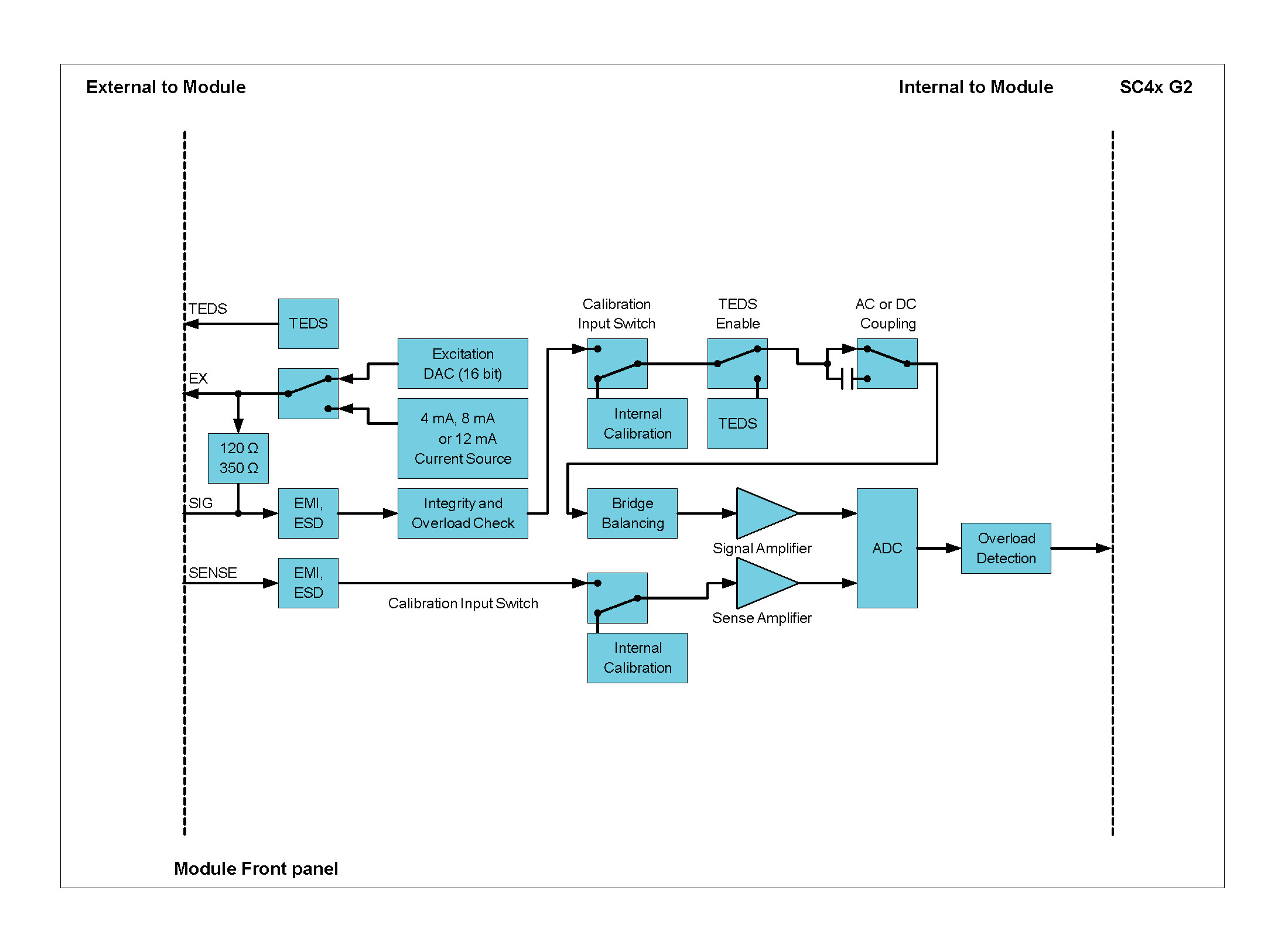
Module grounding
Input signals on the WSB42X are referenced to the Module’s internal ground only. In the figure below the Module’s internal ground is labelled as AGND and the chassis ground of the system is labelled as CGND. A potential difference of up to 50 V may exist between AGND and CGND. Differences in excess of 50 V will activate the Module’s protection circuits and clamp voltage differentials to within safe levels.
For shielded sensors connected to CGND, the positive and negative Signal lines can float to a maximum of 50 V above or below CGND.
A simplified diagram of the signal grounding is shown in the next figure.

This grounding method is applicable to all interface modes, ALI, ICP® and WSB and their individual sub modes.
Voltage sensing
Voltage excitation can be sensed using the sense lines (+Sense and -Sense). Sensing can be performed externally by connecting two dedicated sense lines from the Module to the bridge. Internal sensing refers to the measurement of the excitation voltage within the Module, without the need for external sense wires.
Voltage excitation is measured and digitized to 24-bit resolution using a dedicated ADC. The maximum sampling rate for the sense channel is 204.8 kSa/s under most conditions and generally mirrors the sample rate set for the signal channels.
Voltage excitation sensing allows for accurate initial setting of the excitation voltage.
The following diagrams illustrate voltage excited Wheatstone bridges with external and internal sensing for full, half and quarter bridges.

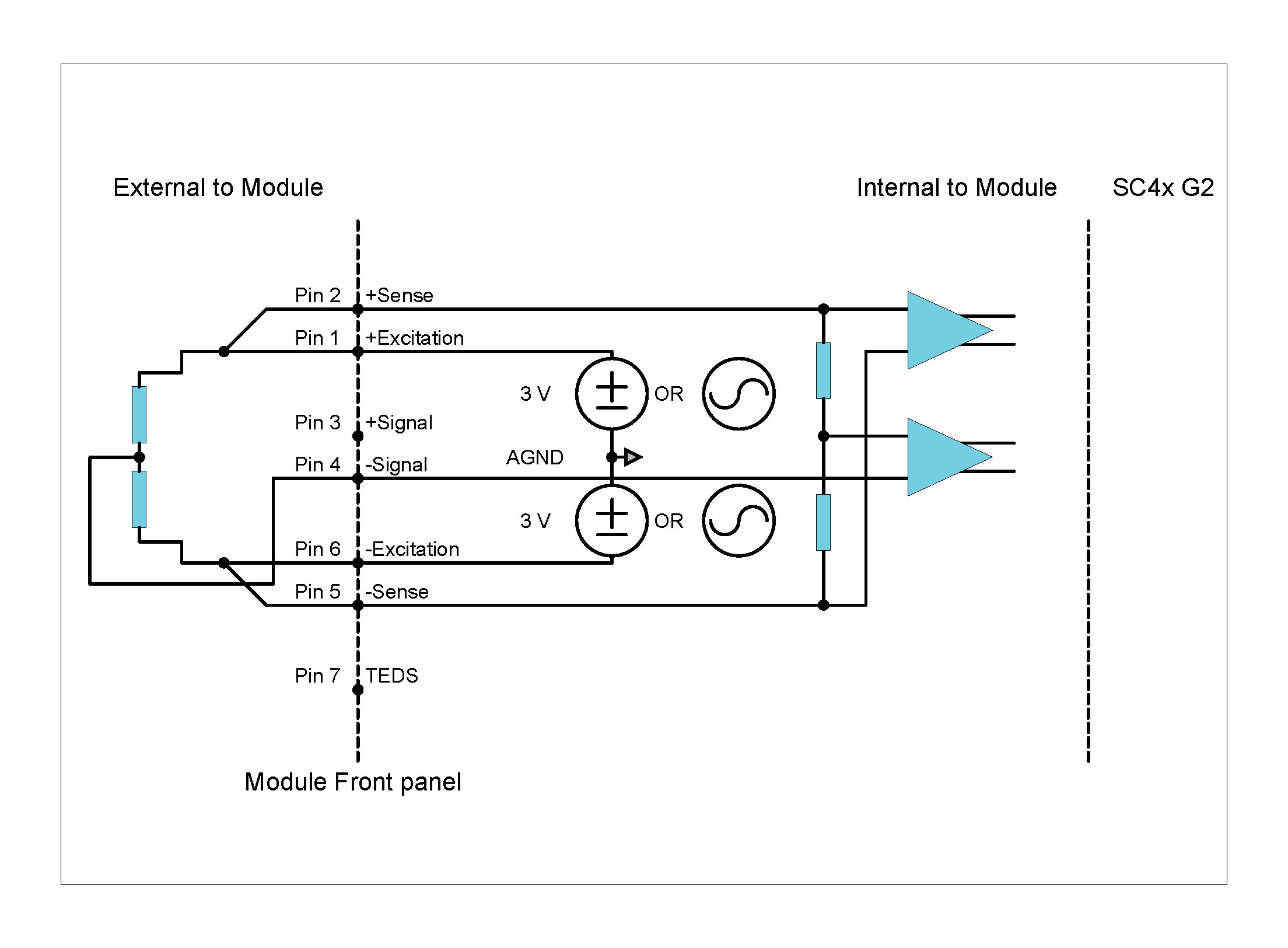
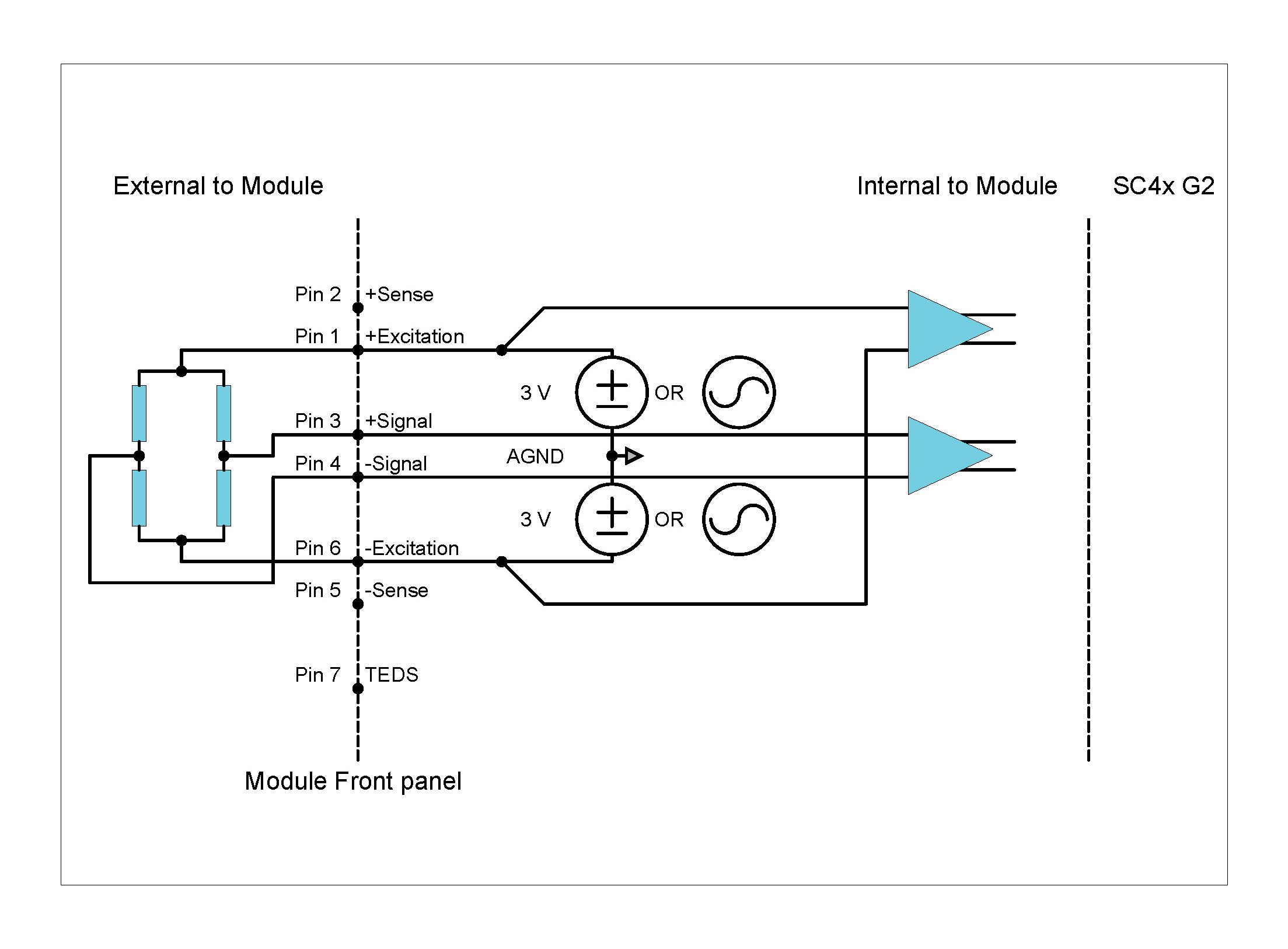
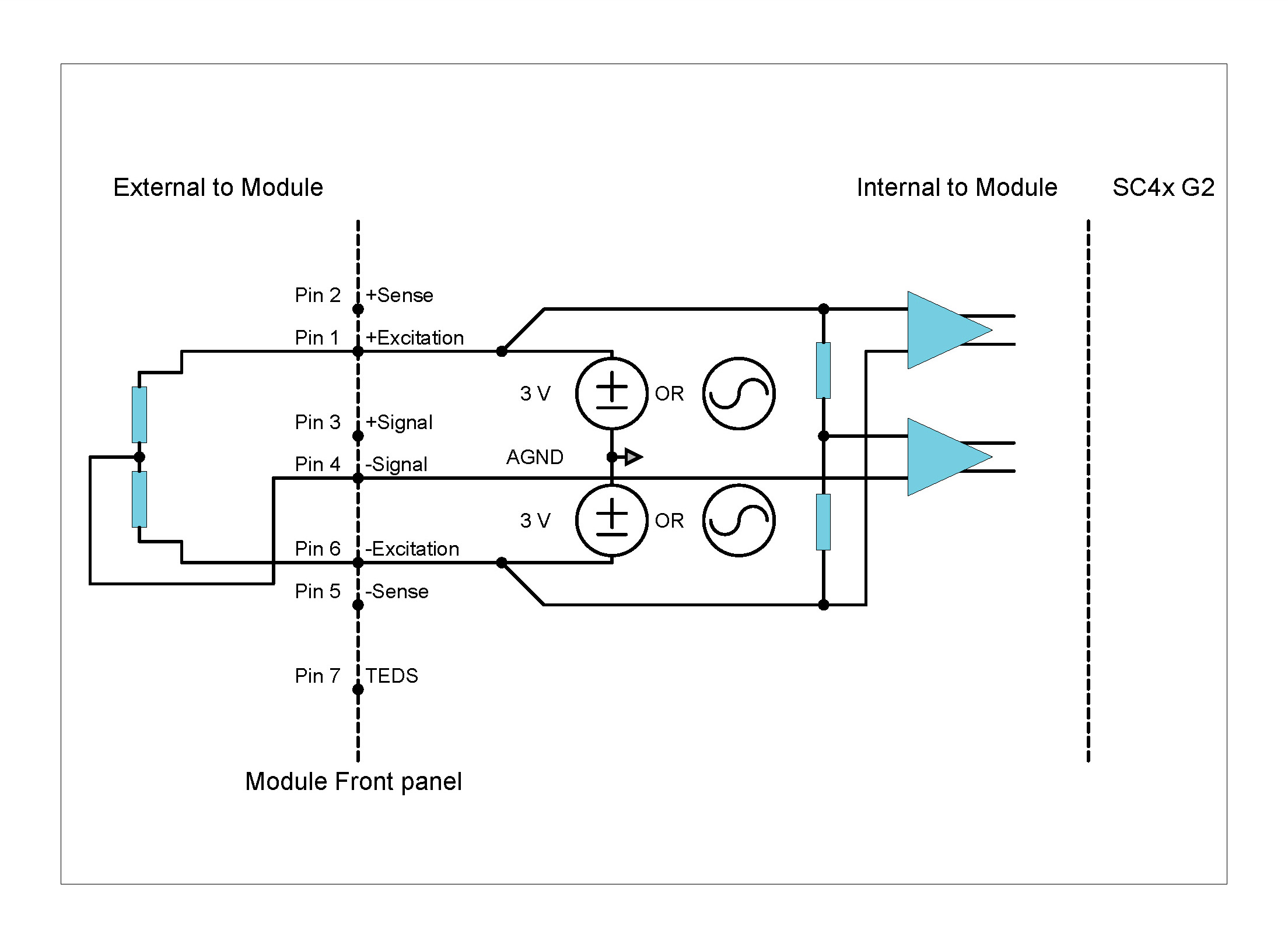
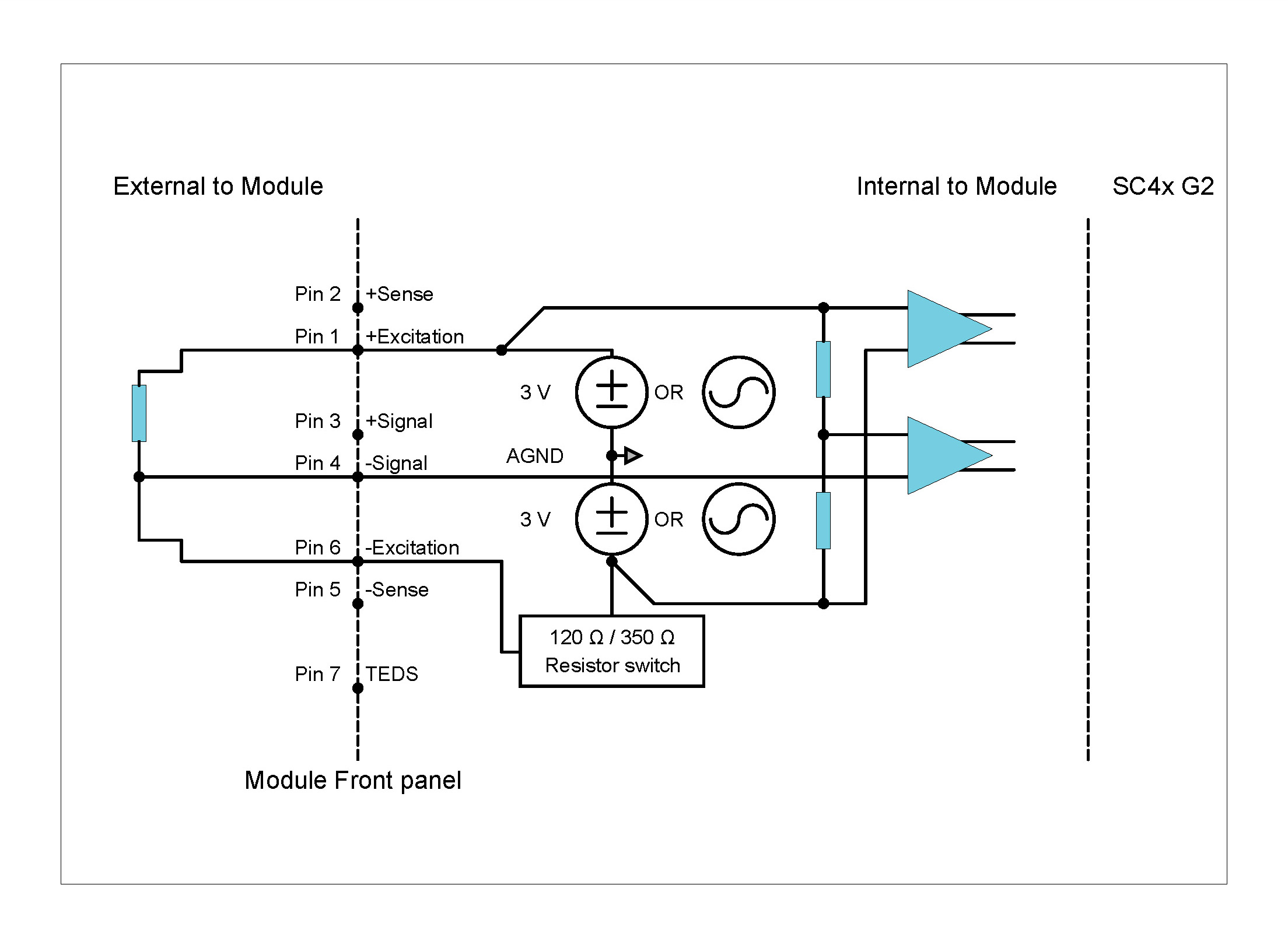
Constant current excitation
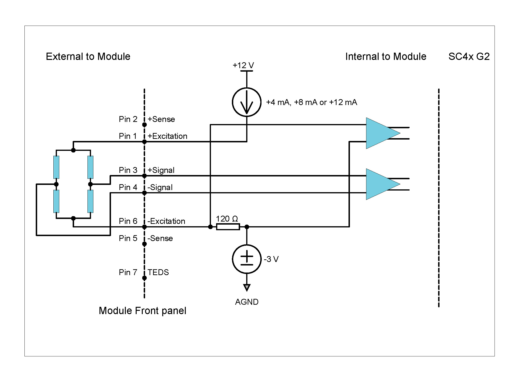

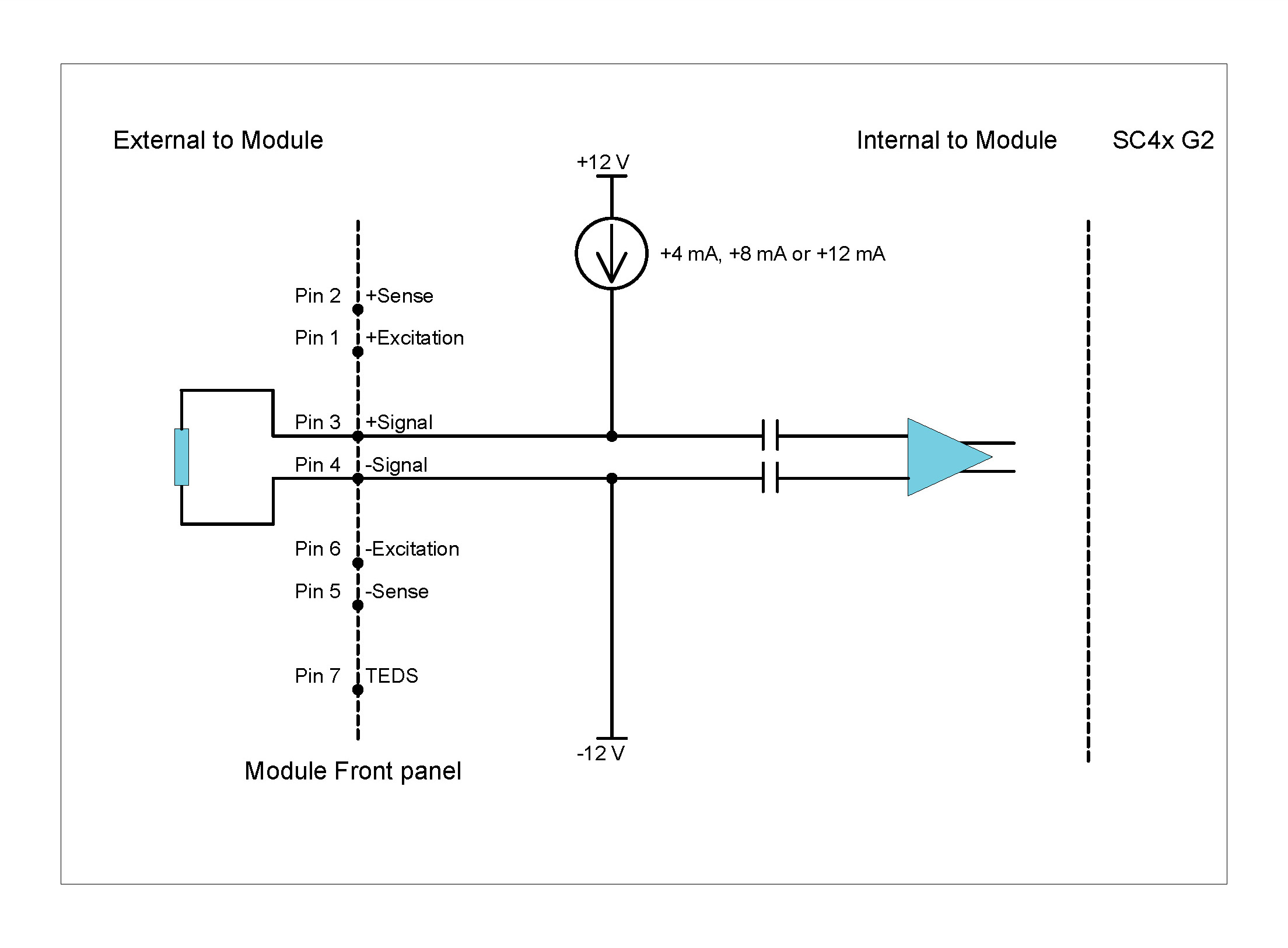
Exciting sensors with 12 mA from ±12 V supplies will add substantially to the Module power consumption. It is recommended that 12 mA excitation only be used to drive long cables in cases where high signal bandwidth is required. The diagrams illustrate typical connection setups for constant current excitation.
Shunt Calibration
Shunt calibration is a means of simulating strain in a bridge. It is an accepted and useful way of checking the gain and accuracy of instrumentation without the need to expose the transducer to known physical input values.
Shunt calibration works by shunting a known resistor across one arm of a Wheatstone bridge. The resulting deviation in bridge output is expressed in mV/V or mV/mA of excitation.
Practically, data obtained from a shunt calibration can be used to check that the instrumentation is operating as expected, that the correct input range is selected and that the correct gauge and scaling factors are used in subsequent calculations.
Shunt calibration can be performed for any bridge setup.
The table below summarizes the shunt calibration outputs for unloaded bridges with negligible lead wire resistance and gauge factor equal to 2.
| Nominal Bridge Resistance (Ω) | Shunt Resistor (kΩ) | Voltage Excited Bridge Output (mV/V) | Current Excited Bridge Output (mV/mA) | Equivalent Microstrain (For a Bridge Factor of 1) | Simulation Type |
|---|---|---|---|---|---|
| 120 | 100 | 0.30 | 0.04 | 599 | Compression |
| 350 | 100 | 0.87 | 0.31 | 1744 | Compression |
| 1000 | 100 | 2.49 | 2.49 | 4950 | Compression |
Shunt calibration outputs
An equivalent shunt calibration circuit for voltage excitation is illustrated in the figure below. The shunt resistor path is highlighted in red.
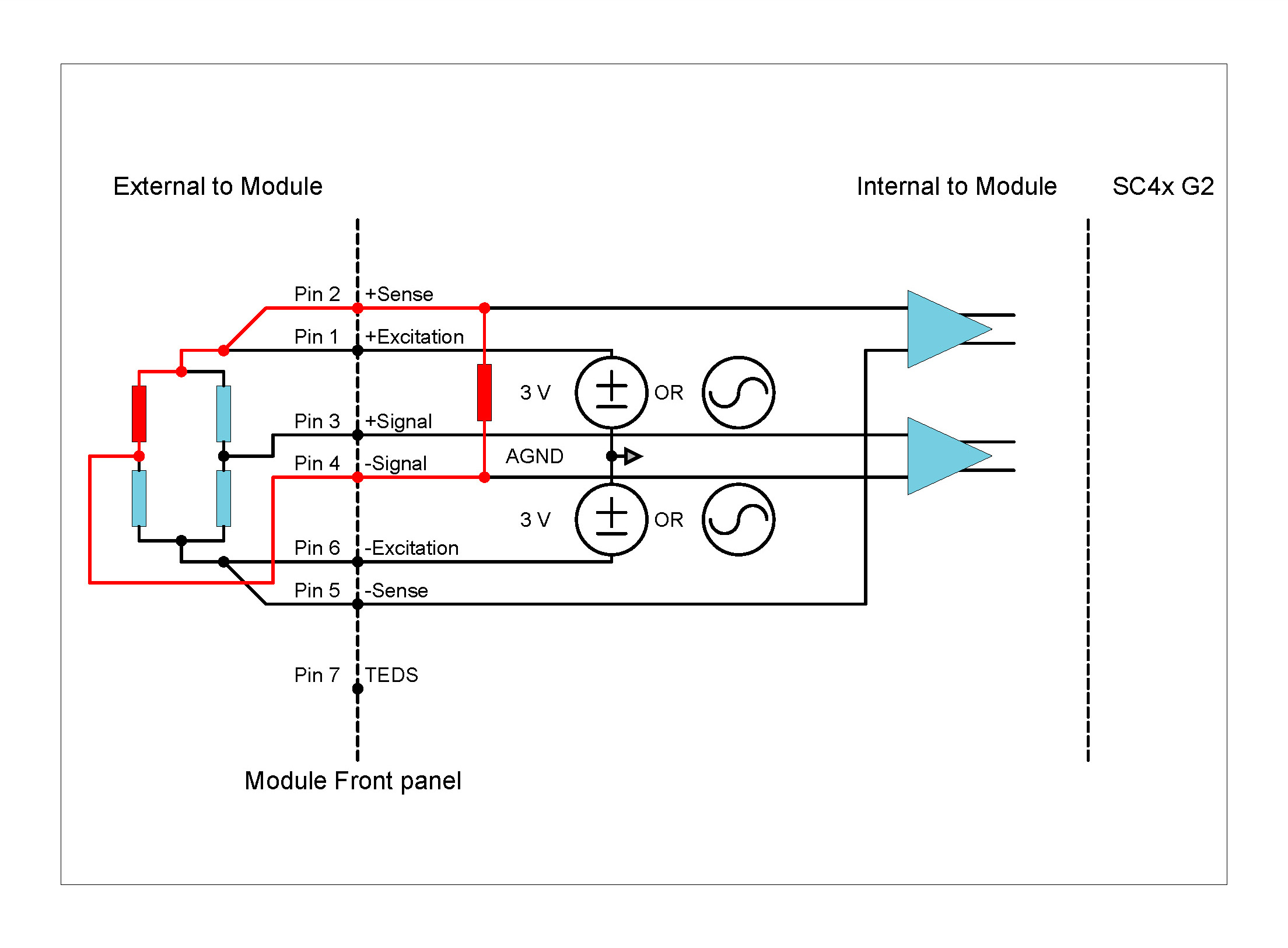
An equivalent shunt calibration circuit for current excitation is illustrated in the figure below. The shunt resistor path is highlighted in red.
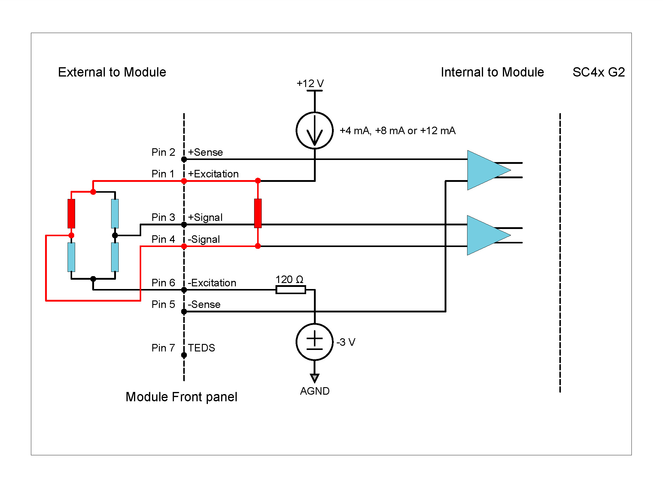
Description
In addition to providing microphone measurements, the MIC42X Module also offers ICP® and voltage input modes. The Module can be used:
| Front Panel | Connector Information and Pin Definitions |
|---|---|
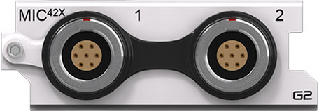 |
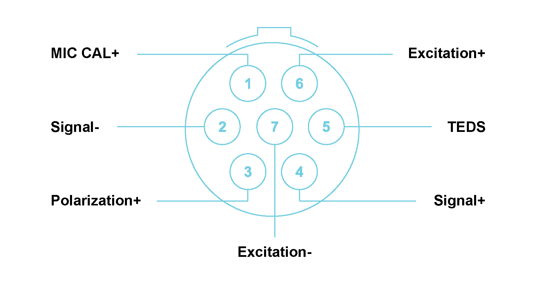 |
MIC42X with LEMO® 7-way EGG.1B connectors Module Pin Definition (when looking into the front panel’s connector or at the rear of the cable’s connector)
Features
Please note:The features and specifications may vary based on the software package utilized with the DECAQ
MIC42X Specifications
| Interface | ICP® | ICP® sensors | |||
| ALI / MIC | For analog source voltages or Microphones | ||||
| Input Coupling | ICP® | AC | |||
| ALI / MIC | DC or AC | ||||
| AC Coupling Frequency Response | ICP® / ALI / MIC | Attenuation | Min | Max | Unit |
| -3 dB | - | 0.16 | Hz | ||
| Other Sampling Rates | Available through digital LP filters and decimation | ||||
| Optional Programmable Digital IIR Filter | Band pass/stop: 6 dB/octave | ||||
| High/Low pass: 12 dB/octave | |||||
| Optional First Order High-Pass Filter | -3 dB @ 1 Hz | ||||
| Module Calibration | Internal amplitude and phase calibration | ||||
| Protection | 2 kV ESD | ||||
| Galvanic Isolation | 50 V | ||||
| Bandwidth | DC to 100 kHz | ||||
| Maximum Sampling Rate (fs) per channel | 204.8 kSa/s | ||||
| A/D Conversion | 24-bit | ||||
| Data Transfer | 16/24-bit | ||||
| Input Voltage Ranges (Peak) | ±120 mV; ±1.2 V; ±12 V | ||||
| ICP® mode | 4 mA; 8 mA or 12 mA constant current at 24 V excitation | ||||
| Input Biasing Settings | Differential Float (Balanced Float) | Both the positive and negative signal inputs are connected through 1 MΩ to floating ground (voltage input mode only) | |||
| Single-Ended Float (Unbalanced Float) | Positive signal input connected through 1 MΩ to floating ground; Negative signal input connected to floating ground | ||||
| Single-Ended GND (Unbalanced GND) | Positive signal input connected through 1 MΩ to ground; Negative signal input connected to ground | ||||
| Input Impedance | Differential | 2 MΩ ‖ 570 pF | |||
| Single-Ended | 1 MΩ ‖ 290 pF | ||||
|
Digital Low-Pass Filter Filter scales with sampling rate |
Passband | fs x 0.46 Hz | |||
| Stopband | fs x 0.54 Hz | ||||
| Passband ripple | fs = 48 kHz | ±0.001 dB | |||
| fs = 96 kHz | ±0.003 dB | ||||
| fs = 192 kHz | ±0.007 dB | ||||
| Stopband attenuation | 120 dB | ||||
|
Phase Accuracy Channels in similar range |
Typical1 | < 0.2° at 10 kHz | |||
MIC42X Specifications
1 Measured in 12 V range at 204.8 kSa/s
MIC42X Specifications continue
| DC Voltage Accuracy | Input Range (Peak) | % Reading + % Range | ||
| ±120 mV | 0.375 % + 0.125 % | |||
| ±1.2 V | 0.065 % + 0.020 % | |||
| ±12 V | 0.074 % + 0.024 % | |||
|
Noise Input terminated by 50 Ω resistor |
Input Range (Peak) | Guaranteed | Typical | |
| 10 Hz to 23 kHz | ±120 mV | < 1.9 µVrms | < 1.6 µVrms | |
| 10 Hz to 49 kHz | < 2.4 µVrms | < 2.1 µVrms | ||
| 10 Hz to 100 kHz | < 3.1 µVrms | < 2.8 µVrms | ||
| 10 Hz to 23 kHz | ±1.2 V | < 6.9 µVrms | < 4.8 µVrms | |
| 10 Hz to 49 kHz | < 7.8 µVrms | < 5.9 µVrms | ||
| 10 Hz to 100 kHz | < 8.8 µVrms | < 7.3 µVrms | ||
| 10 Hz to 23 kHz | ±12 V | < 19.7 µVrms | < 16.3 µVrms | |
| 10 Hz to 49 kHz | < 26.2 µVrms | < 22.4 µVrms | ||
| 10 Hz to 100 kHz | < 48 µVrms | < 37.4 µVrms |
Dynamic Range1 Input terminated by 50 Ω resistor |
Input Range (Peak) | Typical |
| ±120 mV | > 120 dB | |||
| ±1.2 V | > 130 dB | |||
| ±12 V | > 140 dB | |||
|
Amplitude Flatness Relative to 1 kHz Measured up to 0.39 x fs |
Sampling Rate (fs) | Input Range (Peak) |
Attenuation (Input signal level 100 % of full range) |
|
| 51.2 kSa/s | ±120 mV | − 0.03 dB | ||
| 102.4 kSa/s | − 0.10 dB | |||
| 204.8 kSa/s | − 0.35 dB | |||
| 51.2 kSa/s | ±1.2 V | − 0.03 dB | ||
| 102.4 kSa/s | − 0.10 dB | |||
| 204.8 kSa/s | − 0.35 dB | |||
| 51.2 kSa/s | ±12 V | − 0.03 dB | ||
| 102.4 kSa/s | − 0.10 dB | |||
| 204.8 kSa/s | − 0.35 dB | |||
| Crosstalk | Input Range (Peak) | Guaranteed | Typical | |
| ±120 mV | 101 dB | 106 dB | ||
| ±1.2 V | 113 dB | 118 dB | ||
| ±12 V | 117 dB | 122 dB | ||
MIC42X Specifications
1 Dynamic range calculated at sampling rate of 51.2 kSa/s, with a 4096-point FFT.
Specification number: SP151002, Release 2.0. The Module settings and measurement conditions that were used during specification measurements are available on request.
Functionality per Channel

Grounding diagrams for ALI mode
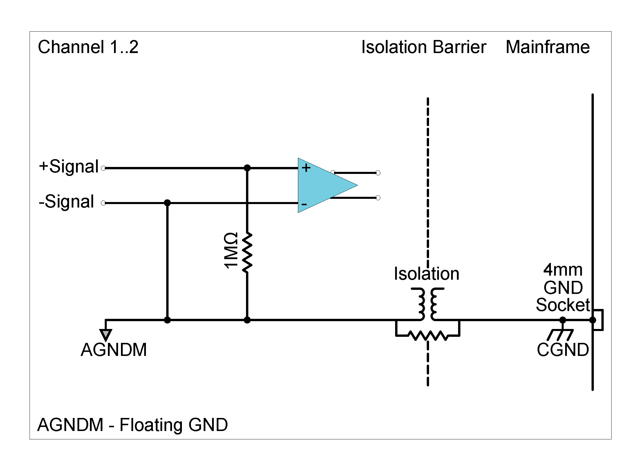
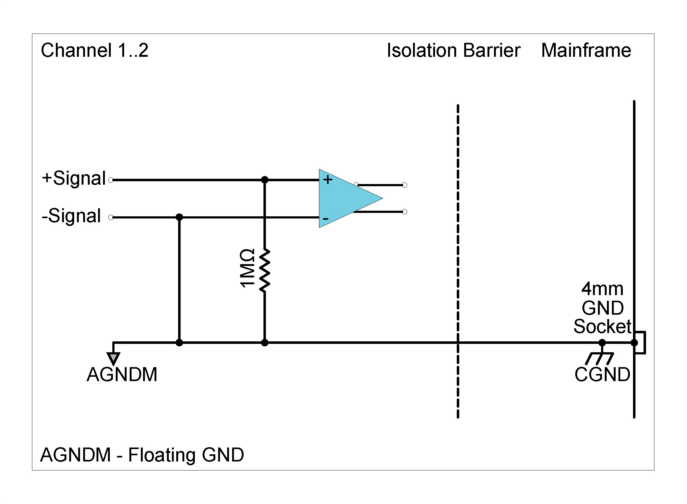
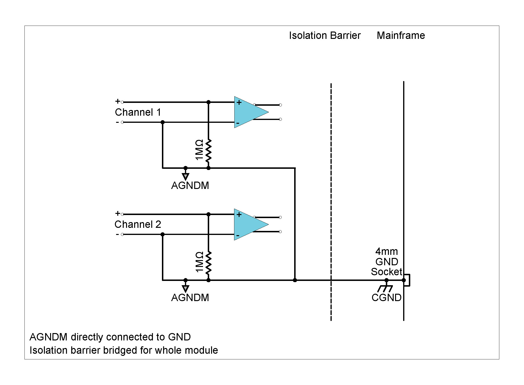
The figure below shows the effect on the Module input mode options when the CGND switch is closed. The isolation barrier will be bridged for the entire Module. Therefore, any channel connected in differential coupling will measure 1 MΩ to CGND and any channel connected in single-ended coupling will be connected with the single-ended GND (unbalanced GND) option.
Grounding diagrams for ICP®mode
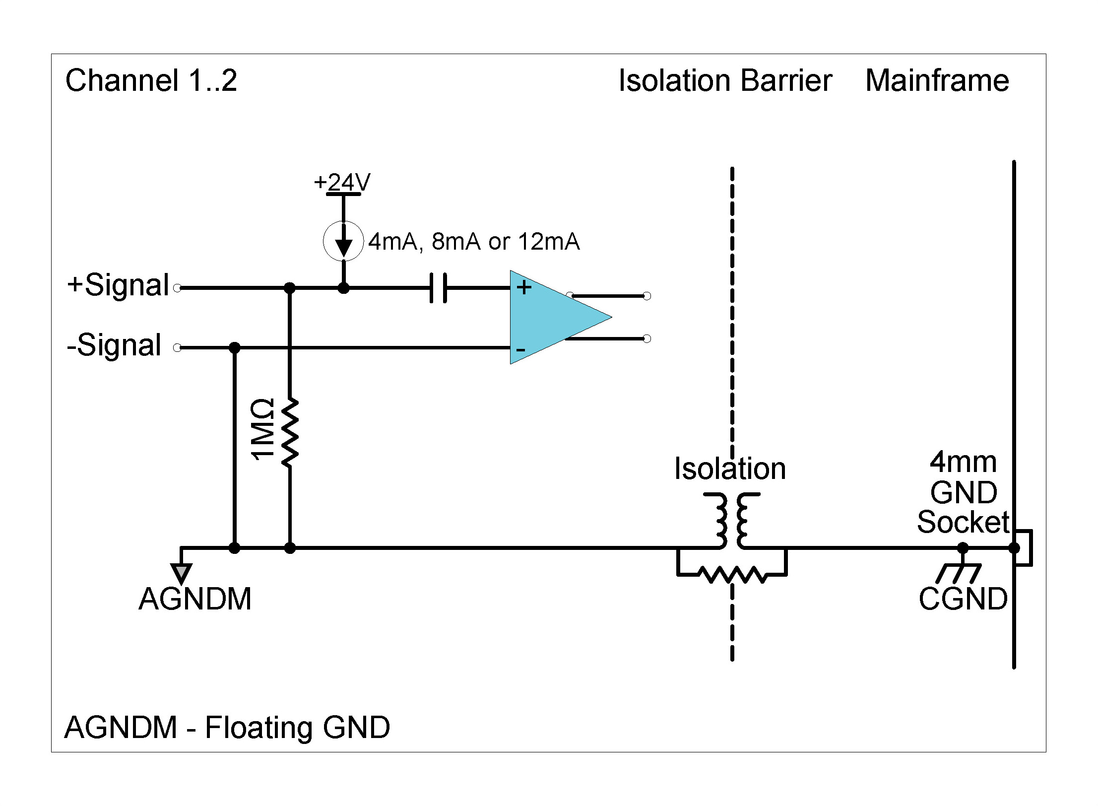
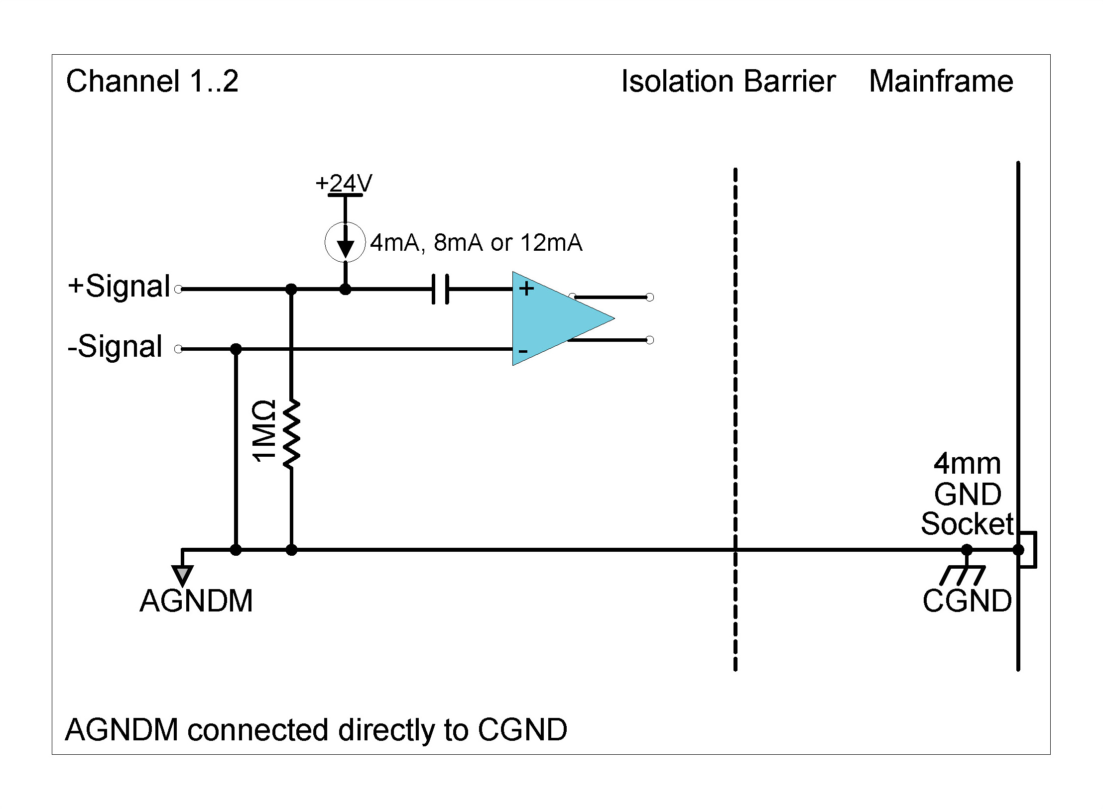
Description
The ALO42S Module provides four independent output channels for the generation of analog signals. Each channel also incorporates Status Input and Output signals, enabling further communication with external equipment for applications such as test supervision or workflow control. The ALO42S Module can be used for applications such as:
| Front Panel | Connector Information and Pin Definitions |
|---|---|
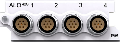 |
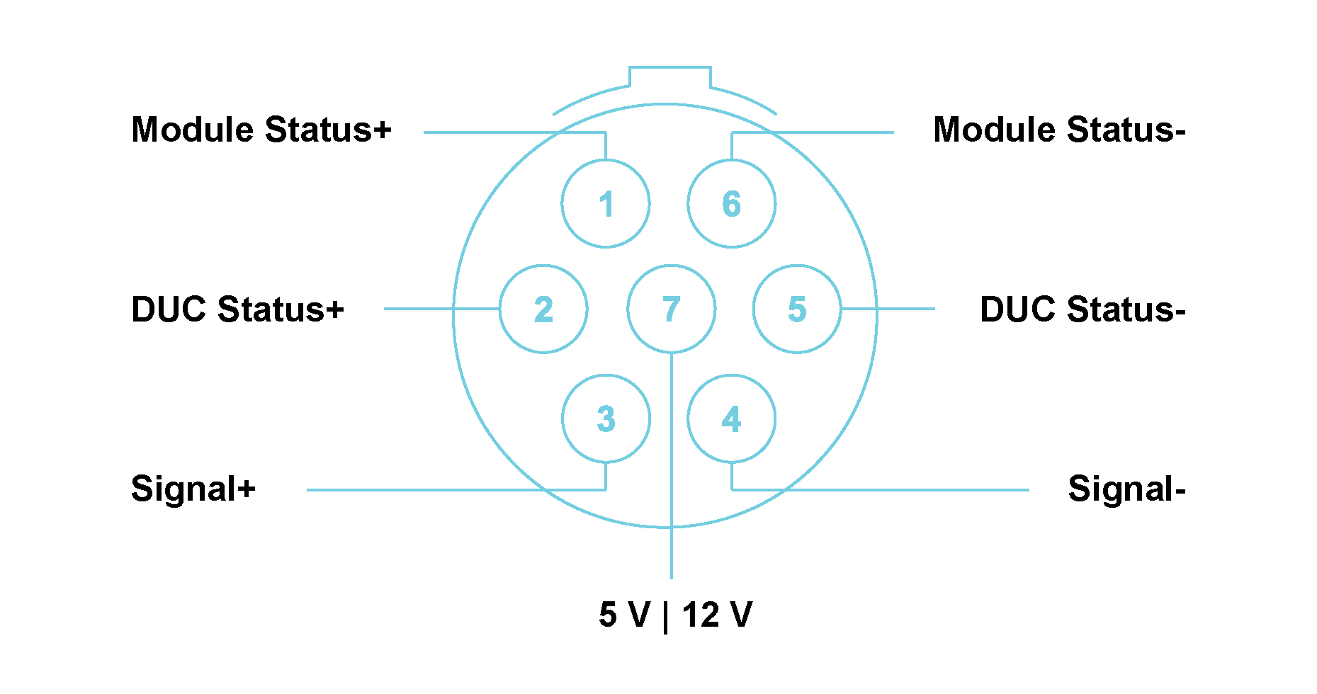 |
ALO42S with LEMO® 7-way EHG.0B connectors Module Pin Definition (when looking into the front panel’s connector or at the rear of the cable’s connector)
Features
Please note:The features and specifications may vary based on the software package utilized with the DECAQ ALO42S Specifications
| Signal Pairs | Module Status + | Module Status - | |
| DUC Status + | DUC Status - | ||
| Signal + | Signal - | ||
| 5 V or 12 V DC | Signal - | ||
|
Device Under Control Status Input Input voltage range: 0 V to 24 V |
Sampling Rate | 15.6 kSa/s | |
| Resolution | 12 bits | ||
| Module Status Output Options | Status |
Relay max 24 V input |
DC Voltage Output 5 V or 12 V |
| Good | Close relay | DC voltage output | |
| Bad | Open relay | No voltage output | |
| DC Voltage Output | Output Voltage | 5 V or 12 V | |
| Output Current | 15 mA (max) | ||
| SubModules | The Quad BNC (QBNC11) SubModule is used to split signals from a 7-way LEMO® connector to 4 BNC connectors. | ||
| The ALOP10 is a rack-mountable SubModule for routing the analog output signals from up to 8 ALO42S Modules to individual male SMB connectors. | |||
| Other Sampling Rate | Available through digital LP filters and decimation | ||
| Module Calibration | Internal amplitude calibration | ||
| Output Biasing Settings | Single-Ended Float or Single-Ended GND (per Module) | ||
| Protection | 2 kV ESD | ||
| Galvanic Isolation | 50 V | ||
ALO42S Specifications continues
| Maximum Sampling Rate (fs) per channel | 204.8 kSa/s | |
| D/A Conversion | 24-bit | |
| Output Voltage Ranges (Peak) | ±10 V | |
|
Phase Accuracy Channels in similar range |
Typical1 | < 0.5° at 10 kHz |
| DC Voltage Accuracy | Output Range (Peak) | % Range |
| ±10 V | 0.27 % | |
| Frequency Accuracy | Output Frequency | % Output Frequency |
| > 100 Hz | 0.025 % | |
ALO42S Specifications
1 Measured in 10 V
range at 204.8 kSa/s
The Module settings and measurement conditions that were used during specification measurements are available on request.
Functionality per Channel
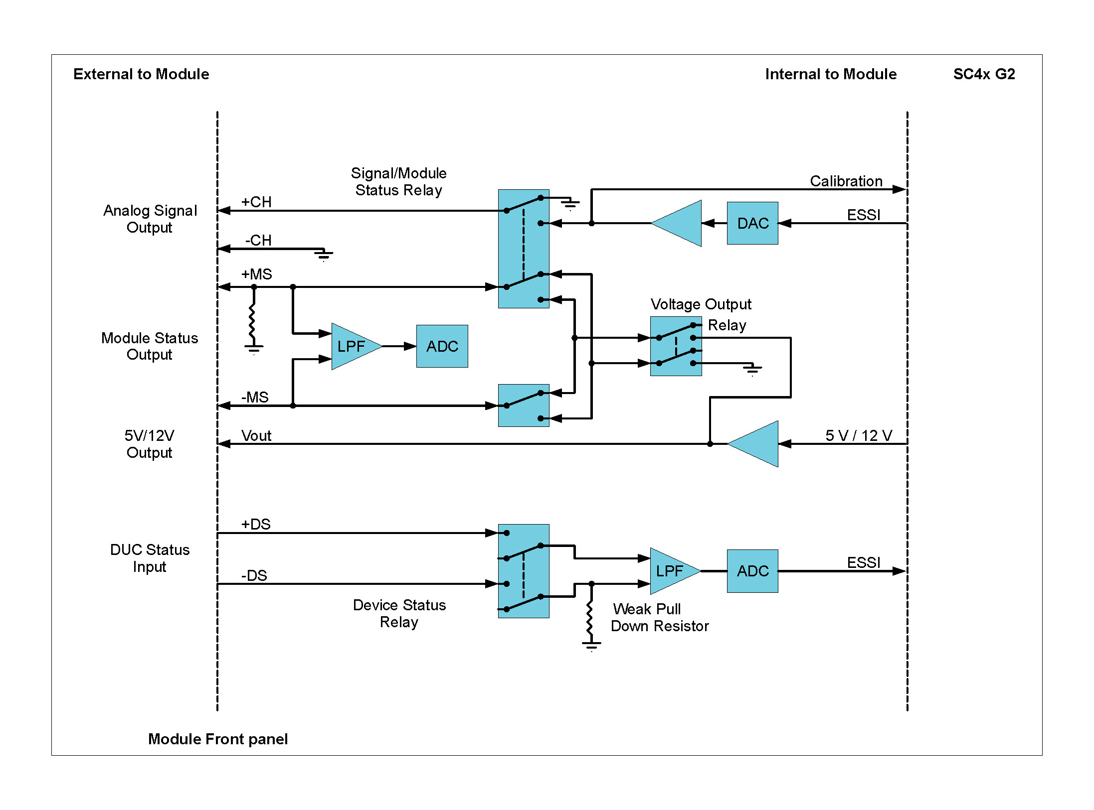
The Device Under Control (DUC) is connected to the ALO42S through a 7-pin LEMO® connector.
Grounding Diagram
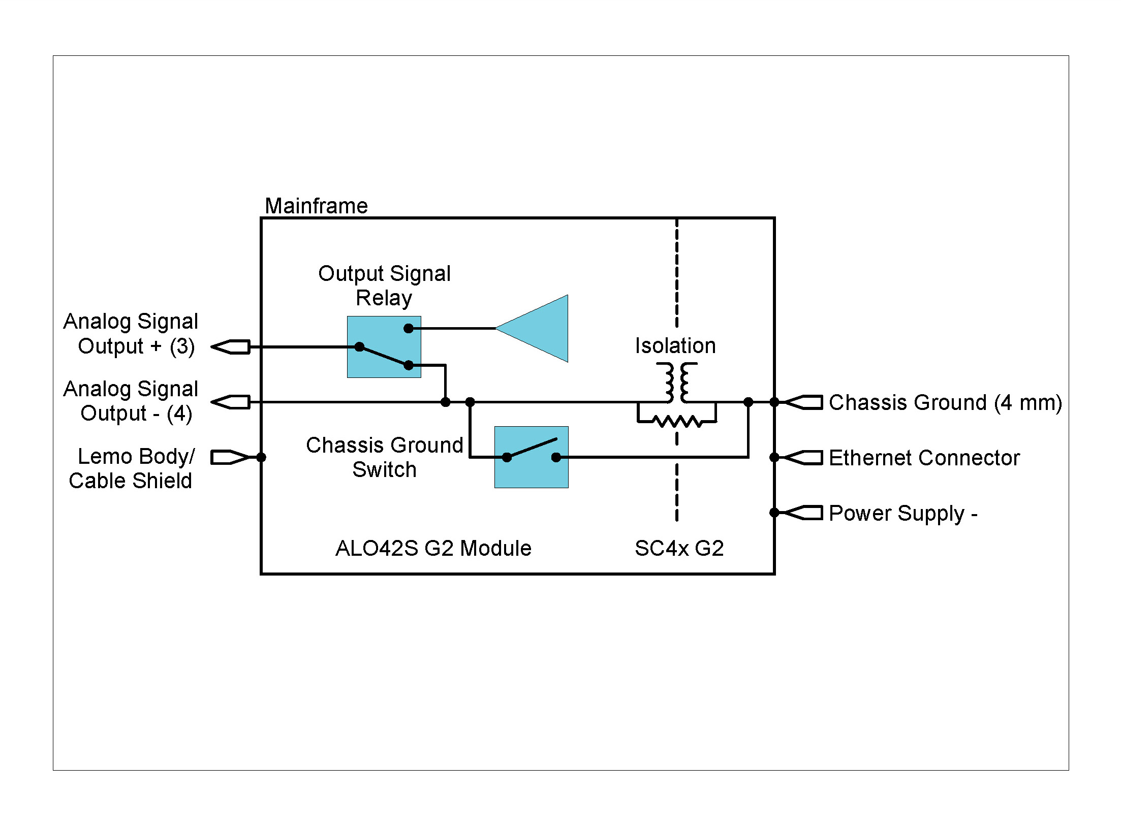
The LEMO® connector on the ALO42S makes contact with the cable shield connecting the DUC. Due to this fact, the shield should be broken on the DUC side, so that the DUC is not connected to the system Chassis Ground.
This LEMO® connector is also connected to the 4 mm Chassis Ground socket on the front right foot of the DECAQ, the Ethernet connector shield and the negative DECAQ power supply pin.
Description
The CAN42S Module provides interfaces to two CAN or CAN FD (CAN with Flexible Data-Rate) busses. CAN FD is an extension of the original CAN (Controller Area Network) protocol, which allows for higher data bandwidth. Messages received from CAN are time-stamped to synchronize their reception with analog and digital measurements from other Modules in the system. A self-reception of sent messages is provided as well as three operational modes, including Participate mode, Listen-Only mode, Self-Reception of sent messages and Loopback mode. The CAN42S Module features independent channel filtering and can be used:
| Front Panel | Connector Information and Pin Definitions |
|---|---|
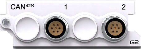 |
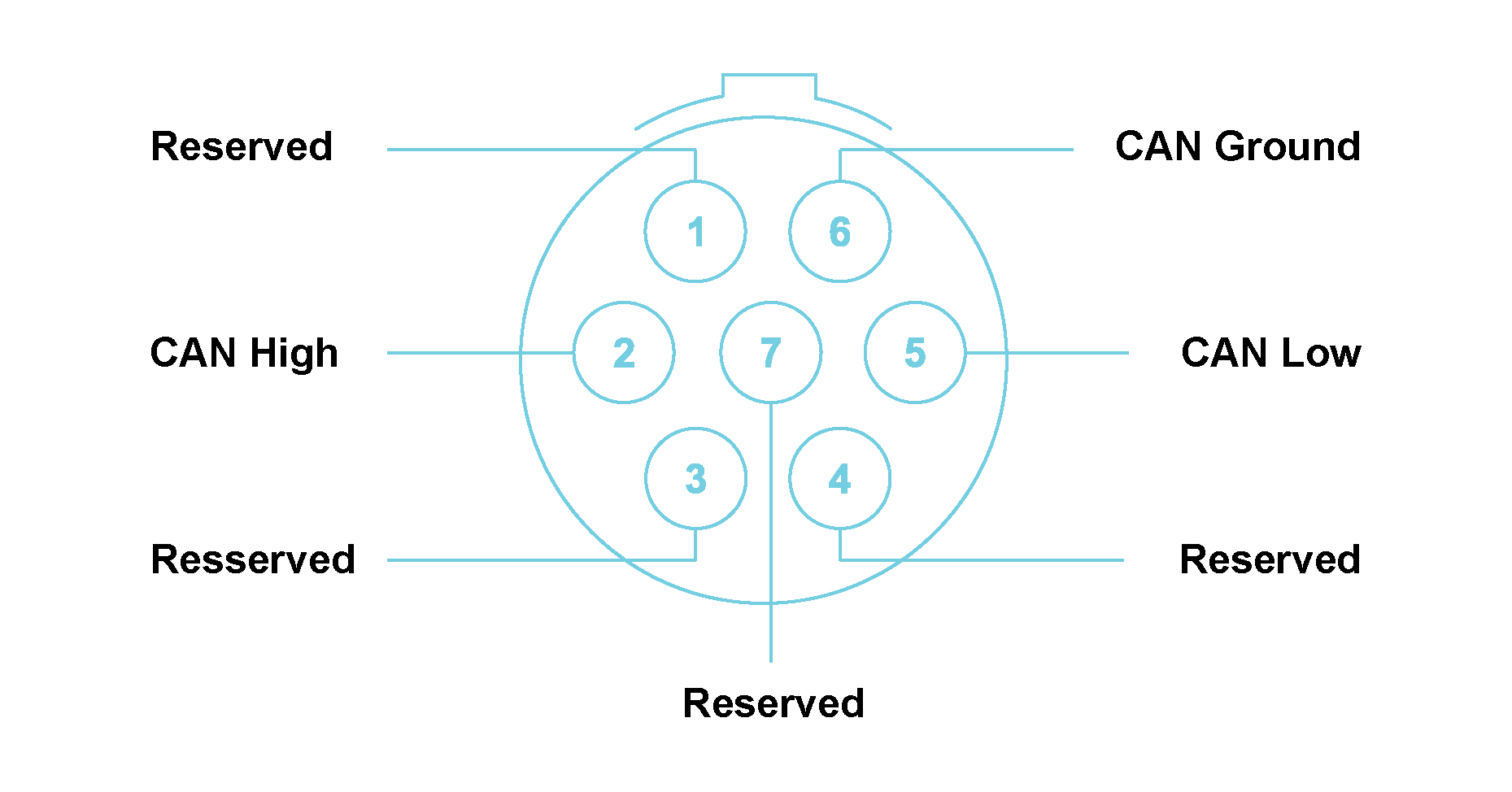 |
CAN42S with LEMO® 7-way EHG.0B connectors Module pin
definition (when looking into the front panel’s connector or at the rear
of the cable’s connector)
Note: Pin 6 – CAN Ground Channel 1 and CAN Ground Channel 2 are isolated from each other.
The CANC10 SubModule can be used to connect a CAN42S Module to a CAN or CAN FD network. It provides the interface between the 7-pin LEMO® connector on the CAN42S Module and the 9-pin D-sub connector on the CAN or CAN FD network.
Two cable lengths are available when connecting to a CAN FD network:
Features
Please note:The features and specifications may
vary based on the software package utilized with the
DECAQ
Functionality per Channel
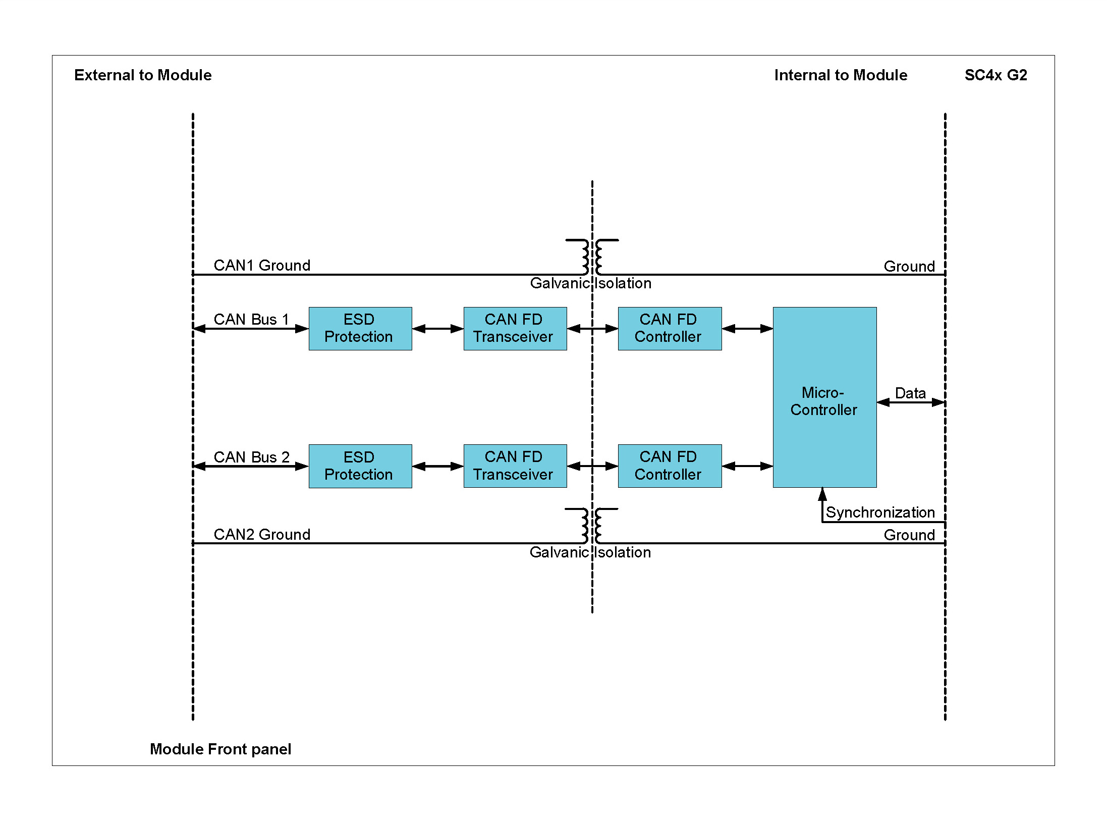
The CAN Module contains two channels that are implemented by its firmware to act as inputs or outputs (channel 1 – input/output 1; channel 2 – input/output 2).
The CAN42S conforms to ISO 11898-1:2015 and to CAN 2.0 B (with support for 11-bit and 29-bit identifiers). Time stamping is executed on each message received which allows CAN messages to be synchronized with the rest of the measurement data.
Grounding Diagram
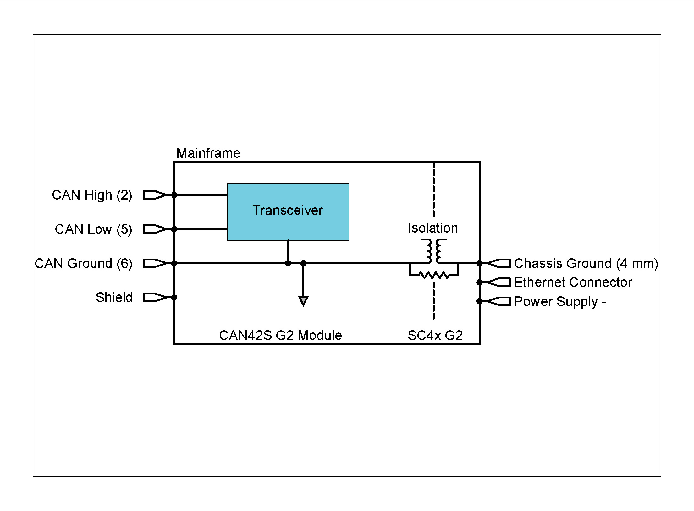
Description
The FLX42 Module provides an interface to connect to a FlexRay™ network for the monitoring of FlexRay™ based messages and interfacing with FlexRay™ based sensors. The FLX42 Module contains two dependent FlexRay™ channel interfaces to support either single channel or dual channel topologies. For the transmission and reception of FlexRay™ messages, selectable bit rates of 2.5, 5, 8 or 10 Mbit/s are available. The FLX42 Module provides independent channel filtering and provides status and error information to the user. The Module can be used:
| Front Panel | Connector Information and Pin Definitions |
|---|---|
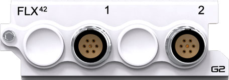 |
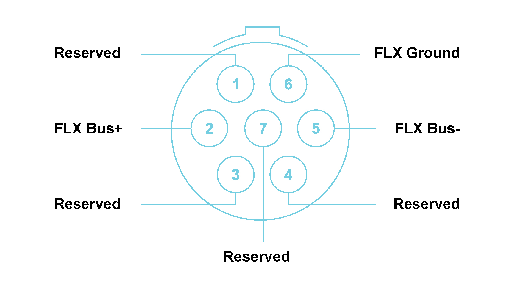 |
FLX42 with LEMO® 7-way EHG.0B connectors Module pin definition (when looking into the front panel’s connector or at the rear of the cable’s connector)
The FLXB20 SubModule can be used to connect the FLX42 Module to a FlexRay™ network.
Two cable lengths are available when connecting to a FlexRay™ network:
Features
Please note:The features and specifications may vary based on the software package utilized with the DECAQ
FLX42 Specifications
| Module Connectors | LEMO® EHG.0B.307 |
| Channel Configuration | 2 dependent channels – Dual Channel Device or Single Channel Device (connector 2 disabled) |
| Operational Modes | Listen-Only Mode / Participate Mode |
| FlexRay™ Compliance |
FlexRay™ Protocol Specification V2.1A. FlexRay™ Electrical Physical Layer Specification V2.1A |
| Termination | Software selectable 110 Ω termination per channel |
| FlexRay™ Transceivers | NXP TJA1080 |
| FlexRay™ Controller | Freescale MFR4310 |
| FlexRay™ Controller Clock Frequency | 40 MHz |
| FlexRay™ Bit Rate Range | 2.5, 5, 8 or 10 Mbit/s (bandwidth limited at 10 Mbit/s in dual channel mode) |
| Timestamp Resolution | 38.1 ns to 59.6 ns |
| Galvanic Isolation | 50 V |
| Operational Temperature | -25 °C to 80 °C |
FLX42 Specifications
Functionality per Channel

The FLX42 Module contains two dependent FlexRay™ channel interfaces to support either the single or dual channel topologies.
The MFR4310 communication controller and TJA1080 transceivers are used on the FLX42 Module. They support the transmission and reception of FlexRay™ messages over a FlexRay™ network with selectable bit rates of 2.5, 5, 8 or 10 Mbit/s.
The FLX42 Module supports independent channel filtering and provides status and error information to the User.
The FLX42 has:
Grounding Diagram
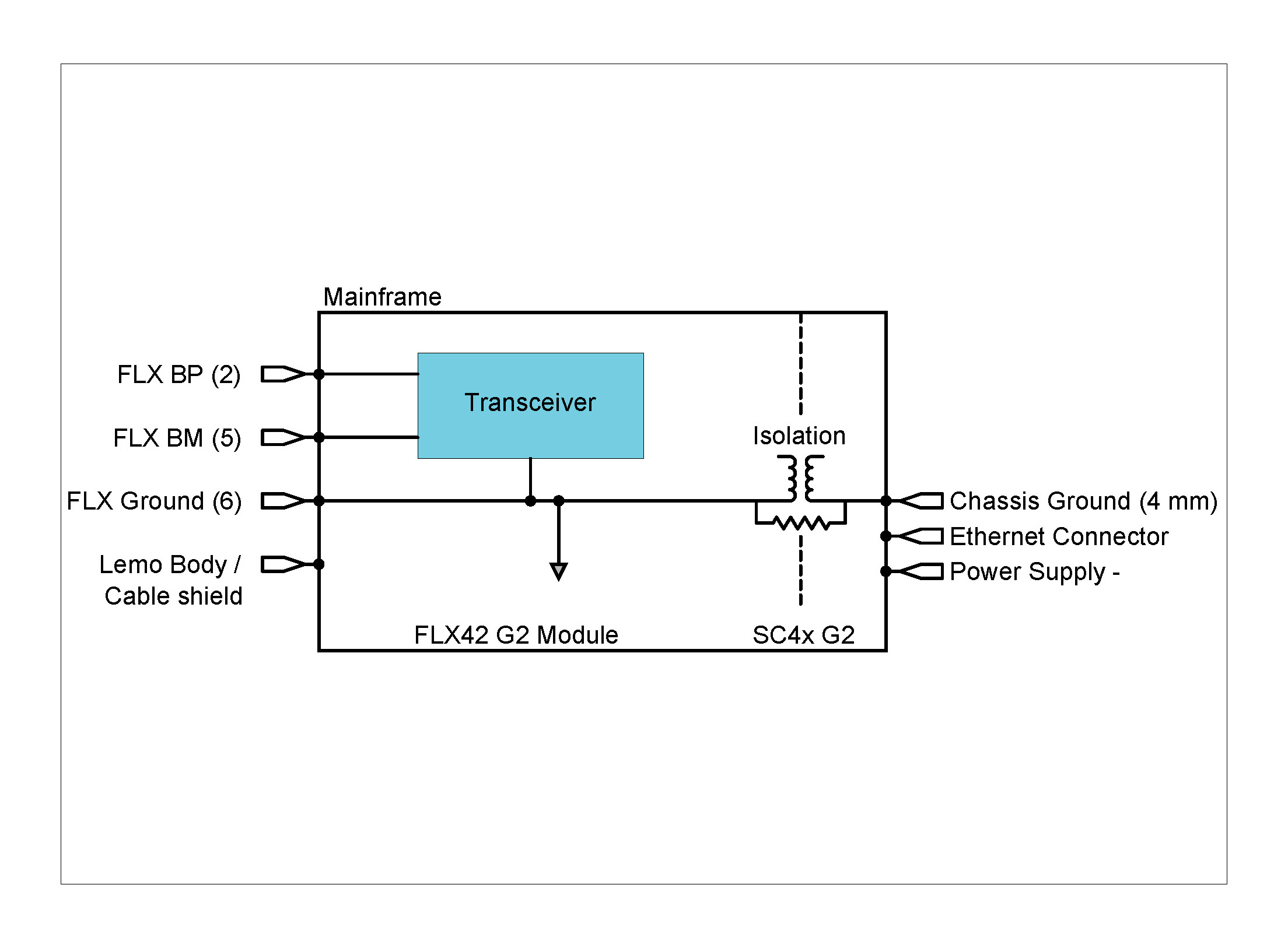
Description
The GPS42S provides accurate GPS time and position data to QuantusSeries systems. Accurate timing information is in the form of a pulse per second (pps) logical signal. The GPS42S can also be used for synchronization purposes. Here the GPS42S Module provides the System Controller with the pps signal to align its internal clock. Systems with this capability are able to synchronize with one another without limitations as to their position or the total number of systems. The Module can be used when:
| Front Panel | Connector Information and Pin Definitions |
|---|---|
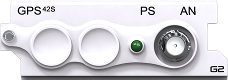 |
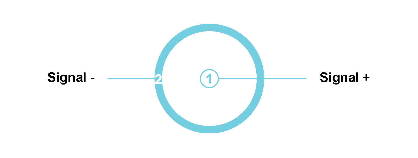 |
GPS42S with an SMA connector Module pin definition (when looking into the front panel’s connector or at the rear of the cable’s connector)
Features
Please note:The features and specifications may vary based on the software package utilized with the DECAQ
GPS42S Specifications
| Number of Channels | 1 |
| Antenna Voltage | 3.3 V |
| Input Connector | SMA |
| Receiver Type | 56 channels GPS L1C/A SBAS L1C/A QZSS L1C/A GALILEO E1B/C |
| Max Update Rate | 4 Hz |
| Position Accuracy | Autonomous 2.5 m CEP , SBAS 2.0 m CEP |
| Acquisition Time |
Cold Start: 29 s; Warm Start: 28 s; Hot Start: < 1 s |
| Available Protocols | NMEA and UBX |
| Operational Limits |
Altitude: < 50 000 m, Velocity < 500 m/s |
| Specified Antenna | ANN-ST-O-005-0 GPS antenna from U-BLOX AG, Switzerland |
| Time stamping of received GPS time and position data | 5 μs |
GPS42S Specifications 1 CEP: Circular Error Probability, the radius of a horizontal circle, centered at the antenna’s true position, containing 50% of the fixes
Functionality
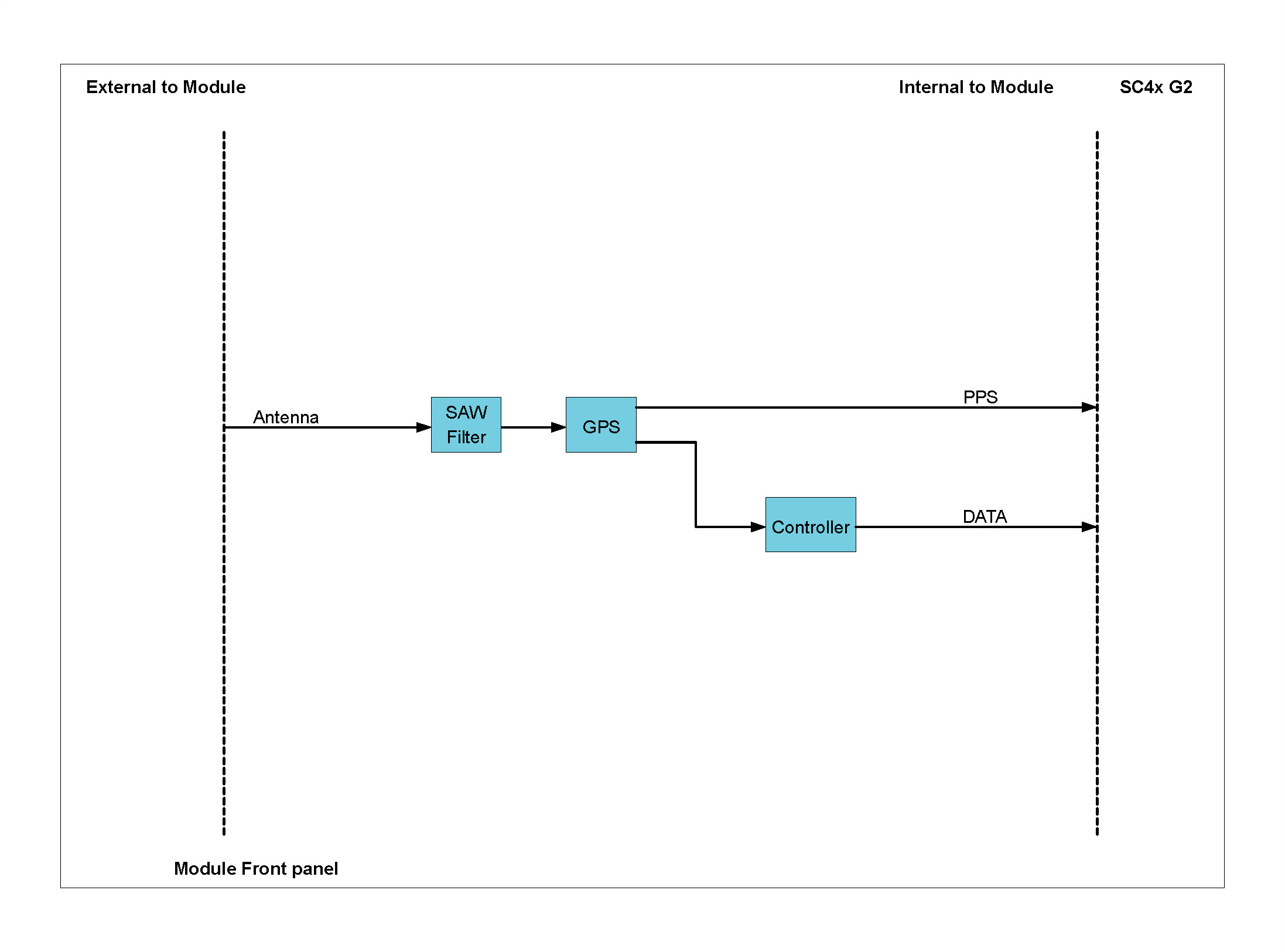
The GPS42S is specified for use with the ANN-ST-0-005-0 GPS antenna. This antenna is an active GPS antenna with a 5 m cable and an SMA Male connector.
The GPS42S implements a real-time differential correction method known as SBAS (or Satellite-Based Augmentation System). SBAS provides correction data for visible satellites as follows:
Using SBAS will allow the GPS42S to achieve an accuracy of < 2.0 m when using circular error probability (CEP). CEP is the probability that 50% of the corrections to the position are within the radius of a horizontal circle centered on the antenna’s true position.
The GPS42S supports drift compensation as well as synchronized start over GPS.
1 ANN-ST-O-005-0 GPS antenna from U-BLOX AG, Switzerland
Inserting a QModule
Removing a QModule
The DECAQ’s S-Port and power connector, as well as most QModules, use LEMO® connectors.
When plugging-in and unplugging LEMO® connectors, please make sure to use the latching sleeve (rough metallic cover) when pulling and pushing in the connector. Do not plug or unplug the LEMO® connectors by pulling on the cable itself. This will damage the cable, affecting measurements.
The following image shows how to plug / unplug the LEMO® connector using the latching sleeve provided:
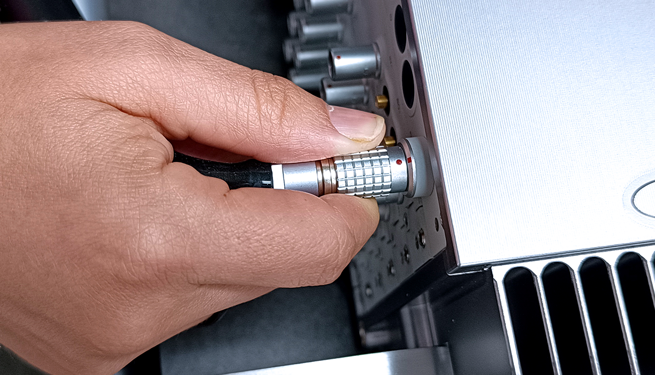
The images below show the incorrect way to plug / unplug the LEMO® connector (by pushing and pulling on a cable). Please take care not to do this:
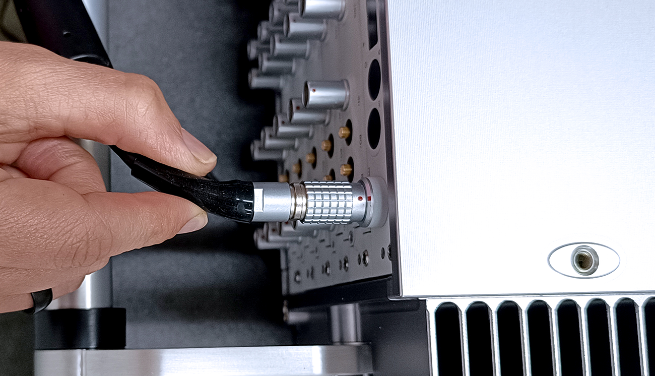
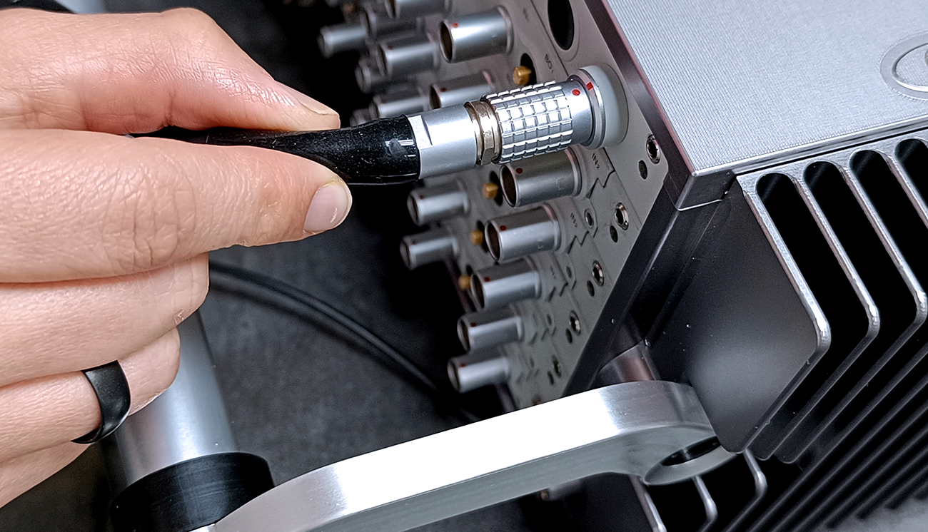
| Product Name | Part Number | Recommended Mating Connector |
|---|---|---|
| CAN42S | LEMO® EHG.0B.307.CLN | 7-pin LEMO® straight plug FGG.0B.307 |
| Product Name | Part Number | Recommended Mating Connector |
|---|---|---|
| ALO42S | LEMO® EGG.0B.307.CLN | 7-pin LEMO® straight plug FGG.0B.307 |
| CHG42S | 10-32 Microdot jack | Microdot screw-on plug |
| CHS42X | LEMO® EHG.0B.309 CLN | 9-pin LEMO® straight plug FGG.0B.309 |
| DCH42S | Twin-BNC receptacle | Amphenol Twin-BNC clamp plug 31-224 or 31-2226 |
| ICP42 | SMB jack (Radiall R114426000) | 50 Ω Radiall SMB plug |
| ICS42 | LEMO® EHG.0B.309.CLN | 9-pin LEMO® straight plug FGG.0B.309 |
| ICT42 | SMB jack (Radiall R114426000) | 50 Ω Radiall SMB plug |
| ICT42S (1) | LEMO® EHG.0B.303.CLN | 3-pin LEMO® straight plug FGG.0B.303 |
| ICT42S (2) | LEMO® EHG.0B.304.CLN | 4-pin LEMO® straight plug FGG.0B.304 |
| MIC42X | LEMO® EGG.1B.307.CLN | 7-pin LEMO® straight plug FGG.1B.307 |
| THM42 | LEMO® EHG.0B.307.CLN | 7-pin LEMO® straight plug FGG.0B.307 |
| WSB42X | LEMO® EGG.0B.307.CLN | 7-pin LEMO® straight plug FGG.0B.307 |
The following section provides mechanical specification overviews and dimensions of the DECAQ’s 2-slot, 3-slot, 4-slot, 6-slot and 10-slot chassis.
| DECAQ 2-slot chassis | |
|---|---|
| Slot 1 | PQ System Board Combined System Controller and Power Supply |
| Slot 2 | SC Signal Conditioning Board: Data Acquisition |
| Number of Channels (if 6 Channels per QModule) | 24 Channels |
| Fan | No |
| External Surface Cooling System | Natural Convection |
| Internal Board’s Cooling System | Conduction |
| Dimensions (W x H x D) | 287 x 64 x 264 mm / 11.30 x 2.52 x 10.39 inches |
| Volume | 4.9 L 1.3 gal |
| Mass Fully Populated with Battery | 5.8 kg 12.78 lb |
| Mass Fully Populated without Battery | 5.2 kg 11.46 lb |
| Battery Type | Li-Ion |
| Number of Battery Cells | 10 |
| Battery Capacity | 90 Wh |
| Minimum Ambient Temperature | -20 °C -4 °F |
| Maximum Ambient Temperature | 62 °C 143.6 °F |
| Humidity (non-condensing) | 90% RH |
| Shock [1] (11 ms duration) | 55 g Vertical 40 g Transverse and Longitudinal |
| Random Vibration [2] (10 to 2000 Hz) | 0.1 g2/Hz Vertical 0.05 g2/Hz Transverse and Longitudinal |
| Power Input Source [3] | External DC supply with an Internal Battery Pack |
| Power Consumption with Most Demanding QModules [4] | 42 W |
| Power Consumption with Most Demanding QModules and Dynamic Charge On | 47 W |
| Battery charging when system is OFF | 85 W |
[1] According to MIL-STD-810G Method 516.6, Procedure I. 1 g = 9.8 m/s2
[2] According to MIL-STD-810G Method 514.6, Procedure I. 1 g = 9.8 m/s2
[3] These values are an indication of the power consumption for typical chassis configurations and are not intended as an explicit specification for the external power supply.
[4] The term ‘most demanding Modules’ is used to denote the following configuration:
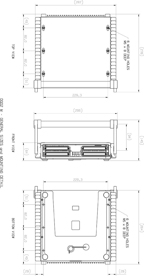
| DECAQ 3-slot chassis | |
|---|---|
| Slot 1 | PQ System Board Combined System Controller and Power Supply |
| Slot 2 | SC Signal Conditioning Board: Data Acquisition |
| Slot 3 | SC Signal Conditioning Board: Data Acquisition |
| Number of Channels (if 6 Channels per QModule) | 48 Channels |
| Fan | No |
| External Surface Cooling System | Natural Convection |
| Internal Board’s Cooling System | Conduction |
| Dimensions (W x H x D) | 307 x 84 x 264 mm / 12.09 x 3.31 x 10.39 inches |
| Volume | 6.8 L 1.8 gal |
| Mass Fully Populated with Battery | 7.8 kg 17.19 lb |
| Mass Fully Populated without Battery | 7.2 kg 15.87 lb |
| Battery Type | Li-Ion |
| Number of Battery Cells | 10 |
| Battery Capacity | 90 Wh |
| Minimum Ambient Temperature | -20 °C -4 °F |
| Maximum Ambient Temperature | 60 °C 140 °F |
| Humidity (non-condensing) | 90% RH |
| Shock [1] (11 ms duration) | 55 g Vertical 40 g Transverse and Longitudinal |
| Random Vibration [2] (10 to 2000 Hz) | 0.1 g2/Hz Vertical 0.1 g2/Hz Transverse and Longitudinal |
| Power Input Source [3] | External DC supply with an Internal Battery Pack |
| Power Consumption with Most Demanding QModules [4] | 64 W |
| Power Consumption with Most Demanding QModules and Dynamic Charge On | 69 W |
| Battery charging when system is OFF | 85 W |
[1] According to MIL-STD-810G Method 516.6, Procedure I. 1 g = 9.8 m/s2
[2] According to MIL-STD-810G Method 514.6, Procedure I. 1 g = 9.8 m/s2
[3] These values are an indication of the power consumption for typical chassis configurations and are not intended as an explicit specification for the external power supply.
[4] The term ‘most demanding Modules’ is used to denote the following configuration:

| DECAQ 4-slot chassis | |
|---|---|
| Slot 1 | PQ System Board Combined System Controller and Power Supply |
| Slot 2 - 3 | SC Signal Conditioning Board: Data Acquisition |
| Slot 4 | Synchronization Board |
| Number of Channels (if 6 Channels per QModule) | 72 Channels |
| Fan | Yes [1] |
| External Surface Cooling System | Natural Convection |
| Internal Board’s Cooling System | Conduction |
| Dimensions (W x H x D) | 307 x 111 x 264 mm / 12.09 x 4.37 x 10.39 inches |
| Volume | 9.0 L 2.38 gal |
| Mass Fully Populated with Battery | 9.1 kg 20.03 lb |
| Mass Fully Populated without Battery | 7.9 kg 17.38 lb |
| Battery Type | Li-Ion |
| Number of Battery Cells | 20 |
| Battery Capacity | 180 Wh |
| Minimum Ambient Temperature | -20 °C -4 °F |
| Maximum Ambient Temperature | 58 °C 136.4 °F |
| Humidity (non-condensing) | 90% RH |
| Shock [2] (11 ms duration) | 55 g Vertical 40 g Transverse and Longitudinal |
| Random Vibration [3] (10 to 2000 Hz) | 0.1 g2/Hz Vertical 0.05 g2/Hz Transverse and Longitudinal |
| Power Input Source [4] | External DC supply with an Internal Battery Pack |
| Power Consumption with Most Demanding QModules [5] | 84 W |
| Power Consumption with Most Demanding QModules and Dynamic Charge On | 92 W |
| Battery charging when system is OFF | 85 W |
[1] For optimal cooling, see Chassis Handling below
[2] According to MIL-STD-810G Method 516.6, Procedure I. 1 g = 9.8 m/s2
[3] According to MIL-STD-810G Method 514.6, Procedure I. 1 g = 9.8 m/s2
[4] These values are an indication of the power consumption for typical chassis configurations and are not intended as an explicit specification for the external power supply.
[5] The term ‘most demanding Modules’ is used to denote the following configuration:

| DECAQ 6-slot chassis | |
|---|---|
| Slot 1 | PQ System Board Combined System Controller and Power Supply |
| Slot 2 - 5 | SC Signal Conditioning Board: Data Acquisition |
| Slot 6 | Synchronization Board |
| Number of Channels (if 6 Channels per QModule) | 120 Channels |
| Fan | Yes [1] |
| External Surface Cooling System | Natural/Forced Convection |
| Internal Board’s Cooling System | Conduction |
| Dimensions (W x H x D) | 307 x 151 x 264 mm / 12.09 x 5.95 x 10.39 inches |
| Volume | 12.3 L 3.25 gal |
| Mass Fully Populated with Battery | 14.7 kg 32.41 lb |
| Mass Fully Populated without Battery | 12.9 kg 28.44 lb |
| Battery Type | Li-Ion |
| Number of Battery Cells | 30 |
| Battery Capacity | 270 Wh |
| Minimum Ambient Temperature | -20 °C -4 °F |
| Maximum Ambient Temperature | 56 °C 132.8 °F |
| Humidity (non-condensing) | 90% RH |
| Shock [2] (11 ms duration) | 55 g Vertical 40 g Transverse and Longitudinal |
| Random Vibration [3] (10 to 2000 Hz) | 0.1 g2/Hz Vertical 0.05 g2/Hz Transverse and Longitudinal |
| Power Input Source [4] | External DC supply with an Internal Battery Pack |
| Power Consumption with Most Demanding QModules | 124 W |
| Power Consumption with Most Demanding QModules and Dynamic Charge On | 134 W |
| Battery charging when system is OFF | 85 W |
[1] For optimal cooling, see Chassis Handling below
[2] According to MIL-STD-810G Method 516.6, Procedure I. 1 g = 9.8 m/s2
[3] According to MIL-STD-810G Method 514.6, Procedure I. 1 g = 9.8 m/s2
[4] These values are an indication of the power consumption for typical chassis configurations and are not intended as an explicit specification for the external power supply.
[5] The term ‘most demanding Modules’ is used to denote the following configuration:
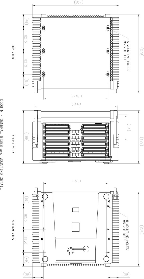
This section contains information about DECAQ chassis handling, from chassis fastening points to effective positioning to ensure your chassis does not overheat.
This section highlights the fitment and operation of the handle for all DECAQ systems. Note that the 10-slot DECAQ does not have a handle.
The handle can be fitted so that it curves either upwards or downwards.
The arms holding the handle in place are curved. The User is able to select which way around the curve flows, either curved up or down.
The position of the handle can be adjusted by pressing in the spring-loaded push buttons at the sides of the handle. When the two black spring-loaded push buttons are depressed slightly, the handle can be rotated into one of three positions (0, 45 or 90 degrees).
The orientation of the handle can be changed so that the handle either curves up or curves down. Once the handle has been removed from the DECAQ, it can be returned either curved upwards or curved downwards.
The sections below highlight each feature of the DECAQ handle.
Shape of the handle
The handle arms on the DECAQ are curved. The User is able to select which way around the curve flows, either curved upwards or downwards.
| Image | Description |
|---|---|
 |
Handle fitted upwards |
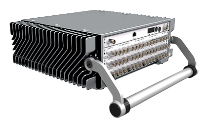 |
Handle fitted downwards |
The push buttons
There is a spring-loaded push button on each side of the DECAQ.
| Image | Description |
|---|---|
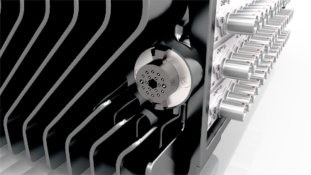 |
The image on the left shows the push button in its “out” position. The User is advised to only carry the DECAQ by the handle when the push buttons are both in their “out” position. |
 |
Depressing the push button half way allows the handle to be rotated. |
 |
Depressing the push button in fully allows the handle to be fitted/removed. |
Fitting the handle
The handle is fitted to a DECAQ using the black spring-loaded push buttons on either side of the system. A hex key is provided on the bottom of the system for ease of handle fitment.
| Image | Description |
|---|---|
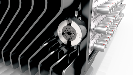 |
Firstly, rotate each push button clockwise into its locked position using the hex key. |
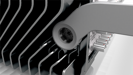 |
Secondly, add the handle over the push buttons. |
 |
Thirdly, rotate each push button anti-clockwise so that each push button moves outwards and clicks into position. In this position, the push button will be flush with the outside of the handle arm. |
Note: The spring-loaded push button sits flush with the outside of the handle arm when the handle has been installed correctly.
Adjusting the position of the handle
Once the handle has been fitted it can be adjusted into one of three positions (0, 45 or 90 degrees). It is not necessary to use the hex key to adjust the position of the handle.
| Image | Description |
|---|---|
|
Depress each push button on either side of the DECAQ until the handle is able to be adjusted. The push buttons need to be pressed in slightly in order to adjust the handle. |
Note: If the push buttons are pressed in fully, the User will be able to remove the handle.
Position of the handle in the upwards direction
When oriented upwards, the handle can be locked into place in one of three positions (0, 45 and 90 degrees).
| Image | Description |
|---|---|
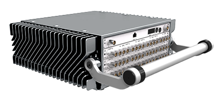 |
Handle locked into position at 0 degrees. |
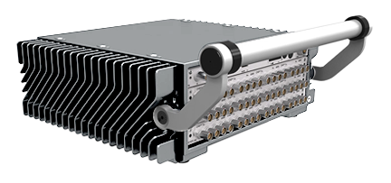 |
Handle locked into position at 45 degrees upwards. |
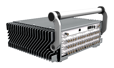 |
Handle locked into position at 90 degrees upwards. |
Position of the handle in the downwards direction
When oriented downwards, the handle can be locked into place in one of three positions:
| Image | Description |
|---|---|
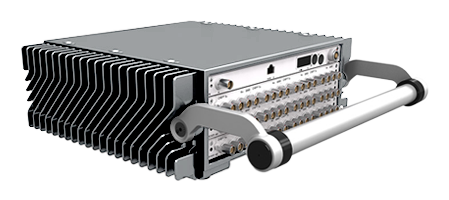 |
Handle locked into position at 0 degrees. |
 |
Handle locked into position at 45 degrees downwards. |
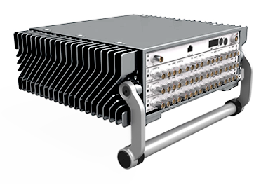 |
Handle locked into position at 90 degrees downwards. |
DECAQ chassis contain six threaded female fastening points on both the top and the bottom faces of the chassis enclosures (the bottom face refers to the face closest to slot 1 of the DECAQ chassis).
The table below provides a summary of information regarding these fastening points:
| Parameter | Value |
|---|---|
| Hole Size | M5 x 8 mm deep |
| Spacing between holes running from front to rear (uniform) | 82 mm |
| Spacing between the right and left sets of holes | 229.3 mm |
| Maximum shear / normal force applied to any screw | 500 N |
Note: The Numbering of VMEbus slots starts at the top.
For more information about the chassis bottom and top views/faces, see Views.
Adhering to the following guidelines is strongly advised to ensure optimal cooling of your system:
The DECAQ’s firmware includes an over-temperature shutdown procedure to protect the system from overheating. Over-temperature protection in the firmware periodically measures the temperature of each QModule and VMEbus board present in the system to determine the maximum overall temperature (MaxTemp or Max) inside the chassis.
The firmware will execute the following actions, depending on the MaxTemp value:
| MaxTemp Value | Action |
|---|---|
| MaxTemp < 70 °C | Fan action: will operate with the user’s speed setting unless the Urgent Cooldown action was triggered. |
| 75 °C ≦ MaxTemp < 85 °C | Fan action: Urgent Cooldown activated. The fan speed will automatically operate at full speed, overriding the user’s speed setting. Once the MaxTemp falls below 70 °C the speed will return to the user’s speed setting. |
| MaxTemp ≧85 °C | Shutdown. The DECAQ will switch off immediately. During shutdown the User Interface Display will show SYSOFF or OFF for a few seconds before shutting down completely. |
Efficient heat transfer from each QModule / VMEbus board into the chassis is extremely important to maintain the system’s optimal functionality.
In order to do that, the user should ensure:
All VMEbus board expanders are fastened properly.
All QModule screws are fastened properly.
This is particularly important if any QModules or VMEbus boards have been recently removed or inserted.
When using RackMounts (to secure 4-, 6- and 10-slot DECAQ chassis in measurement towers), do not obstruct the sides and rear of the RackMount as they have been left open to allow air circulating from the bottom of the rack to cool each chassis sufficiently.
The DECAQ acquires data from its input channels in real-time for subsequent analysis of the data. It uses the following method to synchronize its local clock with an external clock source in order to share a common time base with other systems:
Clock Tuning Synchronization
The DECAQ uses Clock Tuning Synchronization instead of Common Clock Synchronization.
A control loop uses the PTP timing information to train the local oscillator in each DECAQ. After a few cycles, the control loop will lock. Once locked, synchronization requires the control loop to continuously train the local oscillator with small increments.
Two parameters are extracted from the PTP timing protocol, namely ‘Absolute Time’ and ‘Relative Time’. These parameters allow DECAQ systems (and other QuantusSeries systems) to be synchronized. The control loop compares ‘Relative Time’ values to the corresponding values of the tunable oscillator. Over time, the difference between those values is brought as close to zero as possible.
PTP (Precision Time Protocol)
Precision Time Protocol (PTP IEEE 1588-2008) synchronization achieves clock frequency and phase synchronization between multiple DECAQs on the same network. The IEEE 1588-2008 standard ensures high precision, accuracy and robustness, making it perfect for synchronizing measurement systems.
The DECAQ can operate as either a:
The PTP configuration can be done via the software API or the Web Server. The PTP Master Clock is identified using the Best Master Clock Algorithm (BMCA), whereafter all other clocks synchronize directly to the master clock. If no external PTP Master or PTP Grandmaster is available, one of the DECAQ systems will become the PTP Master based on its MAC address or PTP Slave-only setting. If an Ethernet switch is required between a DECAQ system and the PTP master clock, a PTP aware/compliant switch should be used.
Any number of DECAQs can form part of the same system using PTP synchronization. The only criterion is that each DECAQ be connected to the same PTP-enabled network via its Ethernet interface. Network congestion and availability of Ethernet connections dictate the number of DECAQs that can form part of a synchronized Cluster.
The SP45
The SP45 is an Ethernet switch (PTP aware) that can be used in a PTP synchronized network of systems. A PTP aware Ethernet switch minimizes the variability of the latency of PTP timestamp packets that traverse through the switch.
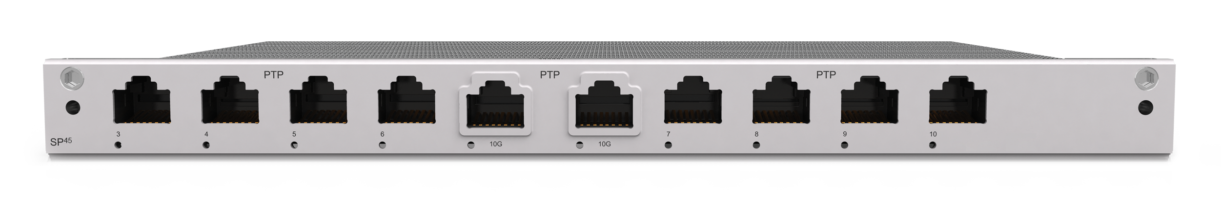
The figure above shows the front panel of the SP45:
Starting from the left-hand side of the board:
The first four ports are Gigabit Ethernet ports. These are used to connect the chassis to the SP45.
The middle two ports are 10 GB Ethernet ports. They are used to attach the SP45 to an existing network.
The last four ports are Gigabit Ethernet ports. These are used to connect the chassis to the SP45.
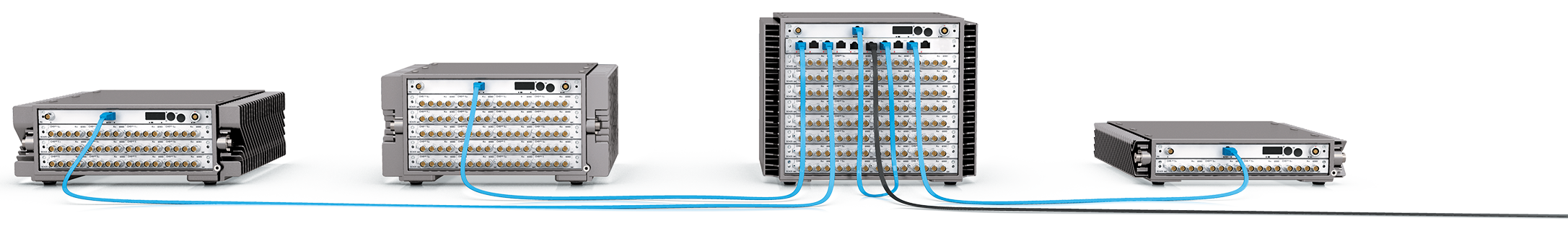
The above image shows a cluster of four chassis synchronized together. The four blue cables connect the chassis to Gigabit Ethernet ports on the SP45. The black cable connects the SP45 to a network.
It’s easy to configure the synchronization setup on DecaQ
To synchronize devices on a PTP network require these devices to share a common configuration of PTP parameters. The SP45 and DecaQ controllers use a predetermined set of PTP configuration parameters. These parameters may not be compatible with other PTP hardware. Please contact Mecalc to find out more on how to integrate with existing PTP networks.
If you are experiencing any problems with your system, please send a web read to support@quantusseries.com or hello@quantusseries.com and our Product Experts will get back to you as soon as possible.
| Overview | An overview of SubModules providing enhanced functionality to corresponding QModules can be found below: |
|---|---|
| ALOP10 | A 32 channel SubModule used with 8 ALO42S Module. Each channel is routed to SMB connectors |
| TBNC10 | The Tri-BNC10 SubModule is used to split signals from a 9-way LEMO® FGG.0B connector to a single triangular prism with 3 BNC connectors |
| TBNC30 | The Tri-BNC30 SubModule is used to split signals from a 9-way LEMO® FGG.0B connector to 3 single BNC Jack connectors to easily connect sensors |
| TBNC40 | The Tri-BNC40 SubModule is used to split signals from a 9-way LEMO® FGG.0B connector to 3 single BNC Plug connectors to easily connect sensors |
| TSMB10 | The Tri-SMB SubModule is used to split signals from a 9-way LEMO® connector to 3 SMB connectors |
| ICTV11 | A single channel SubModule used with an ICT42 or ICT42S Module. It protects a Tacho channel from high voltages |
| FLXB20 | A SubModule which connects a FLX42 Module to a FlexRay™ network, or a CAN42 Module to a CANbus network |
| CANC10 | A SubModule which connects a CAN 42 or CAN42S Module to a CAN or CAN FD bus network |
| SMRM10 | A panel designed to house SubModules |
| PSDP10 | A multiport power panel used to supply power for up to 12 DECAQ Chassis |
| PSDP20 | A multiport power panel used to supply power for up to 12 ALOP10s |
| THMx10 | A single channel SubModule used with a THM42 Module. It is used to connect two thermocouples to a single channel |
| THMP10 | A single channel SubModule used with a THM42 Module. It is used to connect two Pt100 sensors to a single channel |
| THMS10 | A single channel SubModule used with a THM42 Module. It provides 2 sets of 4-way general purpose screw terminals to connect to a pair of E, J, K or T thermocouples or a pair of Pt100 sensors |
| THMS10/250 | The THMS10/250 SubModule is used in conjunction with a THM42 Module. It converts constant current signals between 4 mA and 20 mA to voltages between 1 V and 5 V |
| QBNC11 | A single channel SubModule used with an ALO42S Module. It is used to expand the capacity of the Modules |
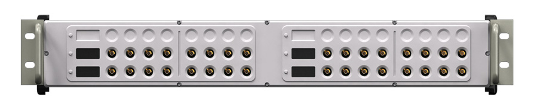
The ALOP10 is a rack mountable SubModule for routing the analog output signals from up to eight ALO42S Modules to individual male SMB connectors. The four 7-pin LEMO® connectors of one ALO42S Module is connected to a 023K cable, which is in turn plugged into the ALOP10 by means of a 37-pin D-sub connector. The analog output signals are routed to a corresponding section of the ALOP10 front panel. Reprogrammable channel numbering is provided for every eighth channel.
Where used:
Signal Cable:
023K The 023K is a standard length signal cable that connects an ALO42S Module to an ALOP10 SubModule
Connection diagram per channel
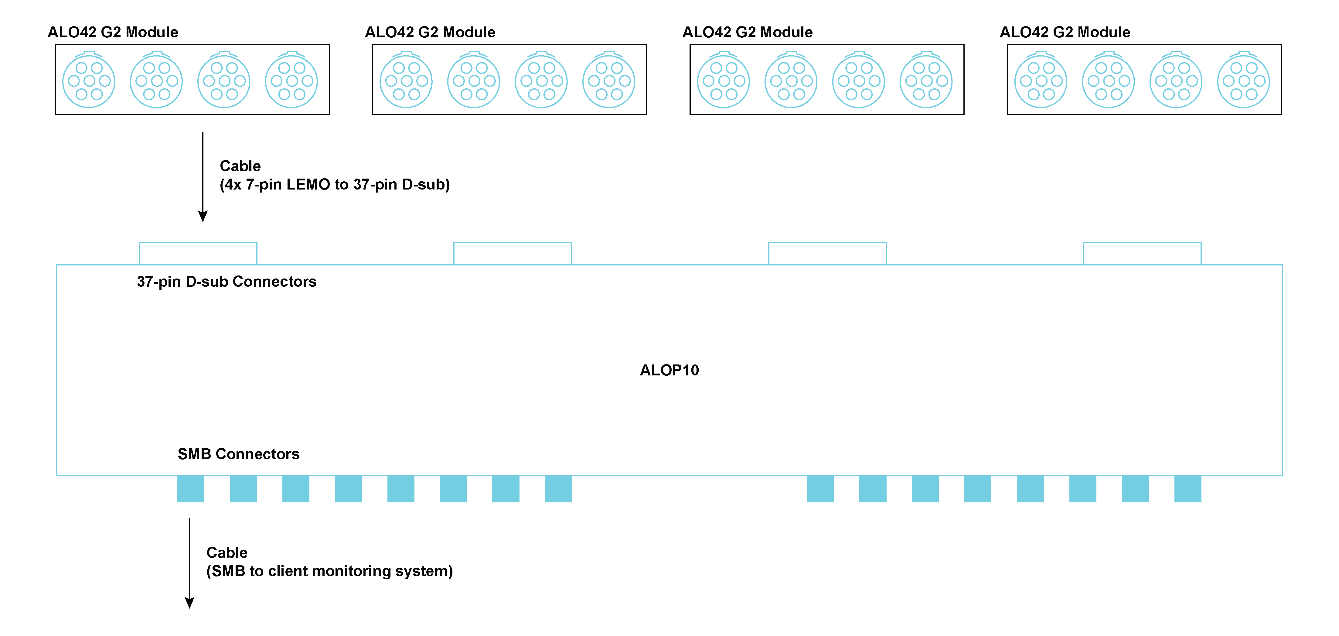
Connector Information and Pin Definitions

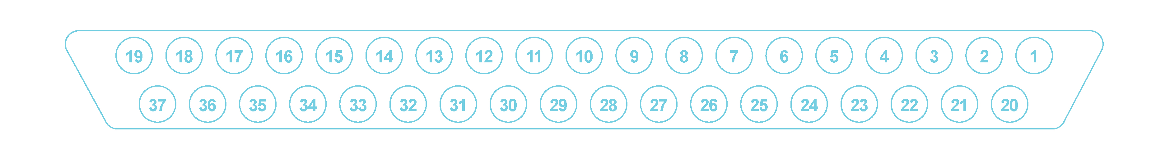
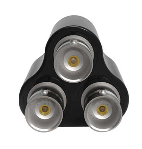
The TBNC10 is used to connect to the ICS42 Module. It splits signals, from a 9-way LEMO® connector on the Module’s front panel, to a single triangular prism with 3 BNC connectors to easily connect sensors. Three BNC connectors are provided on the SubModule to interface to the appropriate triaxial or single axis accelerometer. The SubModule connects to the ICS42 Module through a 300 mm, 500 mm or 1200 mm fly-lead.
| TBNC10 options: | |
|---|---|
| TBNC10 300 | The BNC Jack connectors connect to the ICS42 Module with a total cable length of 300 mm |
| TBNC10 500 | The BNC Jack connectors connect to the ICS42 Module with a total cable length of 500 mm |
| TBNC10 1200 | The BNC Jack connectors connect to the ICS42 Module with a total cable length of 1200 mm |
Where used:
Connection diagram per channel
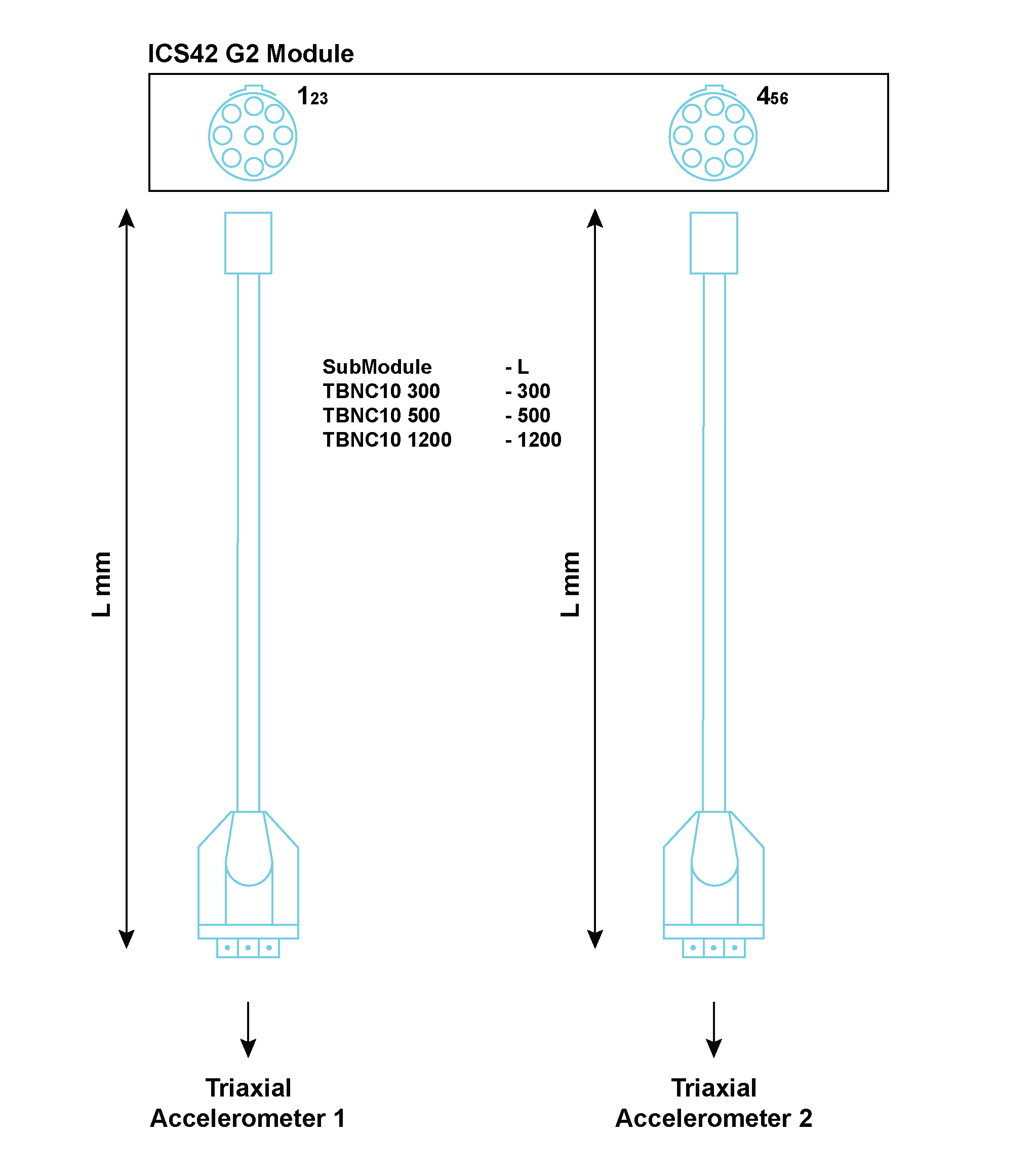
Connector Information and Pin Definitions
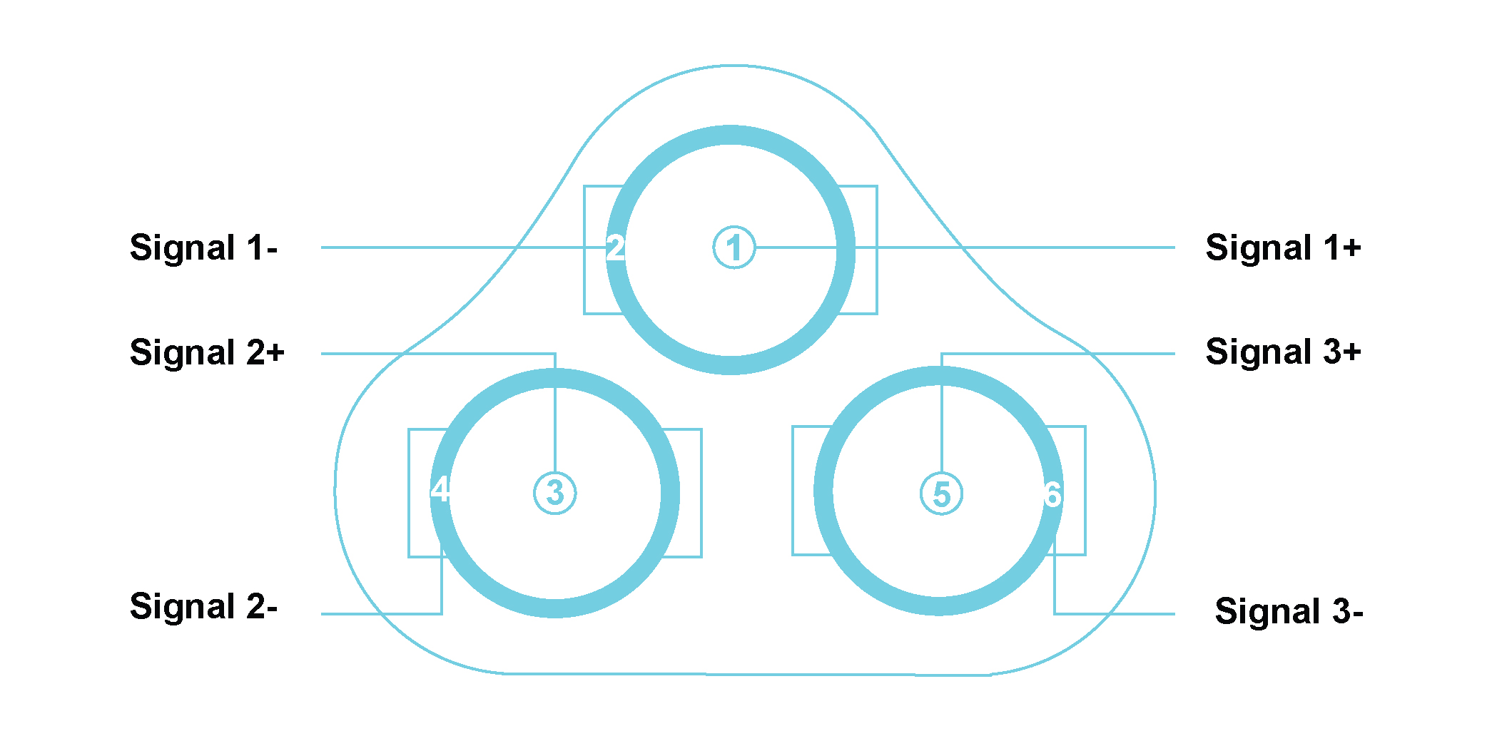
| Pin Number of TBNC10 | Signal Name | Channel on ICS42 | Triaxial Accelerometer pin | |
| Left Lemo® | Right Lemo® | |||
| 1 | Signal 1+ | Channel 1+ | Channel 4+ | X+ |
| 2 | Signal 1- | Channel 1- | Channel 4- | GNDx |
| 3 | Signal 2+ | Channel 2+ | Channel 5+ | Y+ |
| 4 | Signal 2- | Channel 2- | Channel 5- | GNDy |
| 5 | Signal 3+ | Channel 3+ | Channel 6+ | Z+ |
| 6 | Signal 3- | Channel 3- | Channel 6- | GNDz |
Pin descriptions of TBNC10, ICS42 and triaxial accelerometer
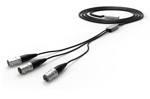
The TBNC30 is used to connect to the ICS42 Module. The Tri-BNC30 SubModule splits signals from a 9-way LEMO® FGG.0B, connecting on the Module’s front panel, to 3 single BNC Jack connectors to easily connect sensors. Three BNC Jack connectors are crimped on cables to provide a flexible interface to the appropriate triaxial or single axis accelerometer. The SubModule connects to the ICS42 Module through a 500 mm or 1200 mm fly-lead.
| TBNC30 options: | |
|---|---|
| TBNC30 500 | The BNC Jack connectors connect to the ICS42 Module with a total cable length of 500 mm |
| TBNC30 1200 | The BNC Jack connectors connect to the ICS42 Module with a total cable length of 1200 mm |
Where used:
Connection diagram per channel
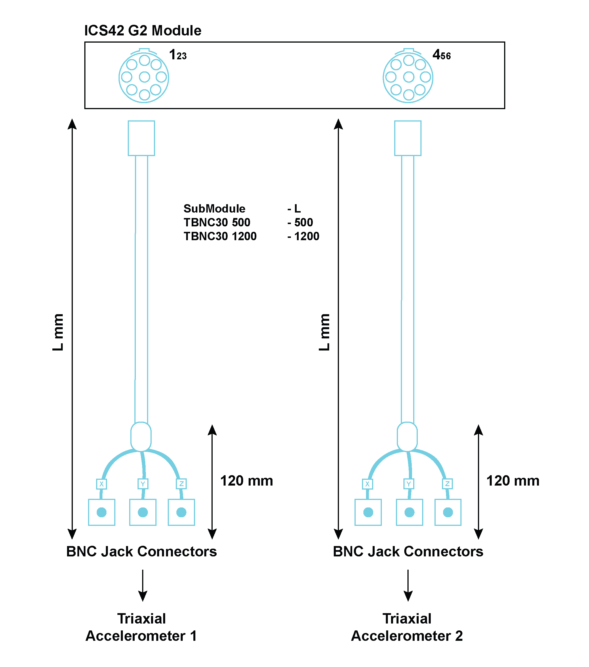
Connector Information and Pin Definitions
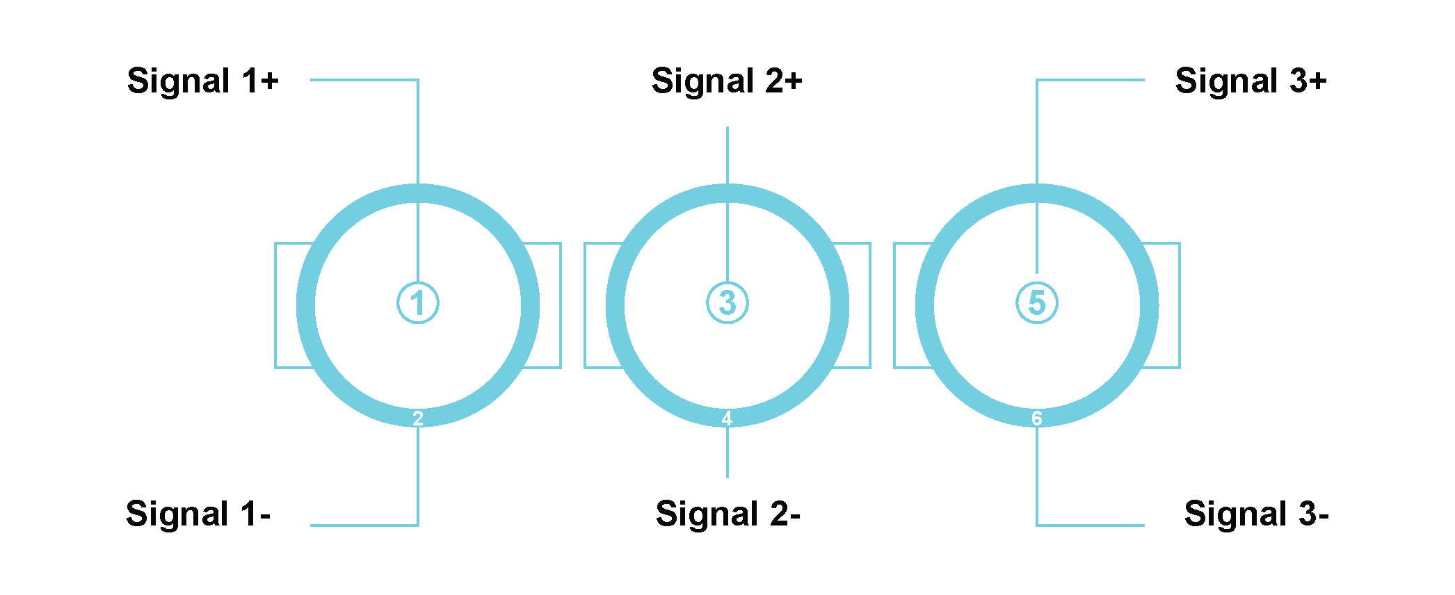
| Pin Number of TBNC30 | Signal Name | Channel on ICS42 | Triaxial Accelerometer pin | |
| Left Lemo® | Right Lemo® | |||
| 1 | Signal 1+ | Channel 1+ | Channel 4+ | X+ |
| 2 | Signal 1- | Channel 1- | Channel 4- | GNDx |
| 3 | Signal 2+ | Channel 2+ | Channel 5+ | Y+ |
| 4 | Signal 2- | Channel 2- | Channel 5- | GNDy |
| 5 | Signal 3+ | Channel 3+ | Channel 6+ | Z+ |
| 6 | Signal 3- | Channel 3- | Channel 6- | GNDz |
Pin descriptions of TBNC30, ICS42 and triaxial accelerometer
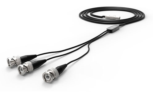
The TBNC40 is used to connect to the ICS42 Module. The Tri-BNC40 SubModule splits signals from a 9-way LEMO® FGG.0B, connecting on the Module’s front panel, to 3 single BNC Plug connectors to easily connect sensors. Three single BNC Plug connectors are crimped on cables to provide a flexible interface to the appropriate triaxial or single axis accelerometer. There are two lengths options available:
| TBNC40 options: | |
|---|---|
| TBNC40 500 | The BNC Plug connectors connect to the ICS42 Module with a total cable length of 500 mm |
| TBNC40 1200 | The BNC Plug connectors connect to the ICS42 Module with a total cable length of 1200 mm |
Where used:
Connection diagram per channel
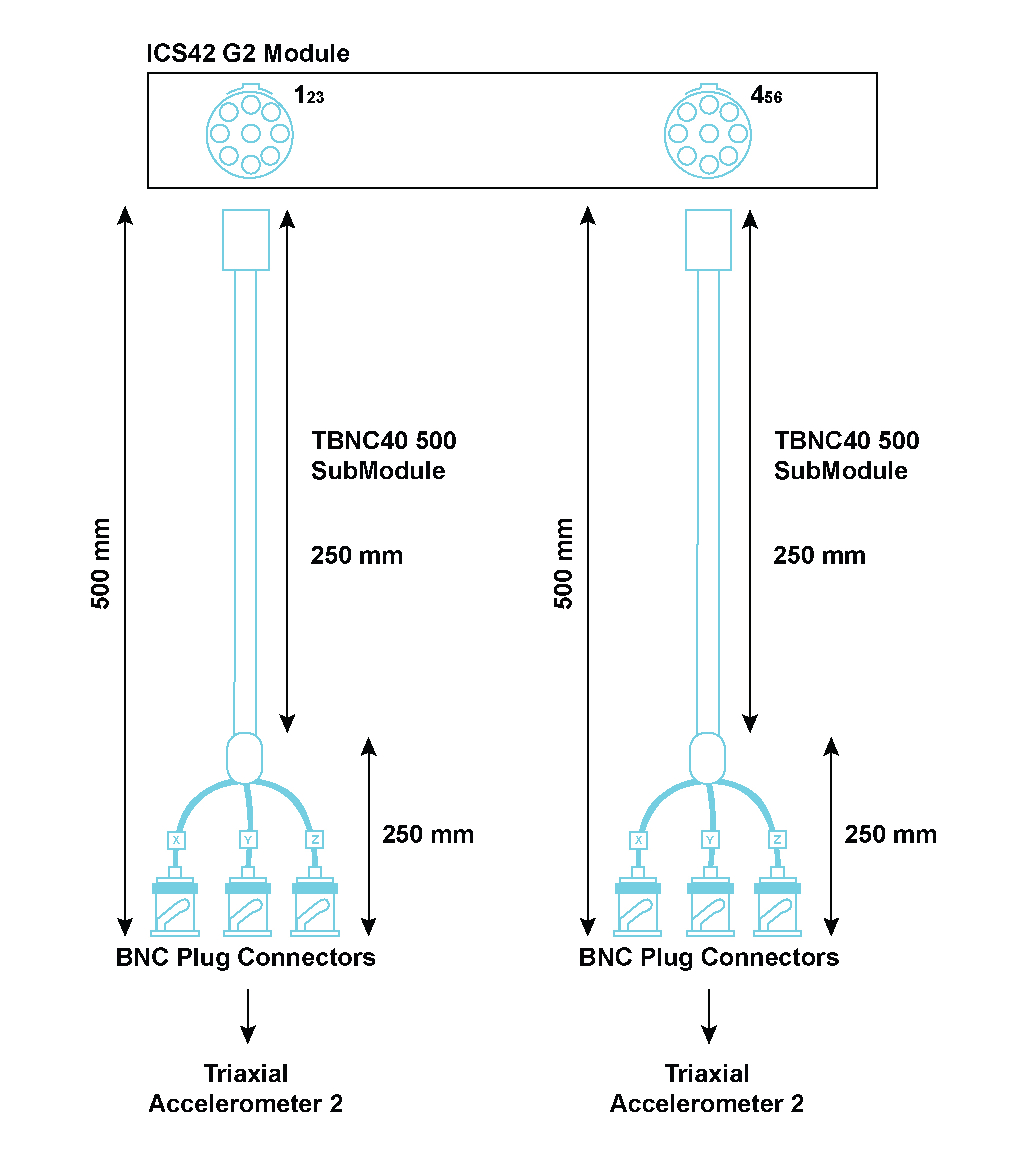
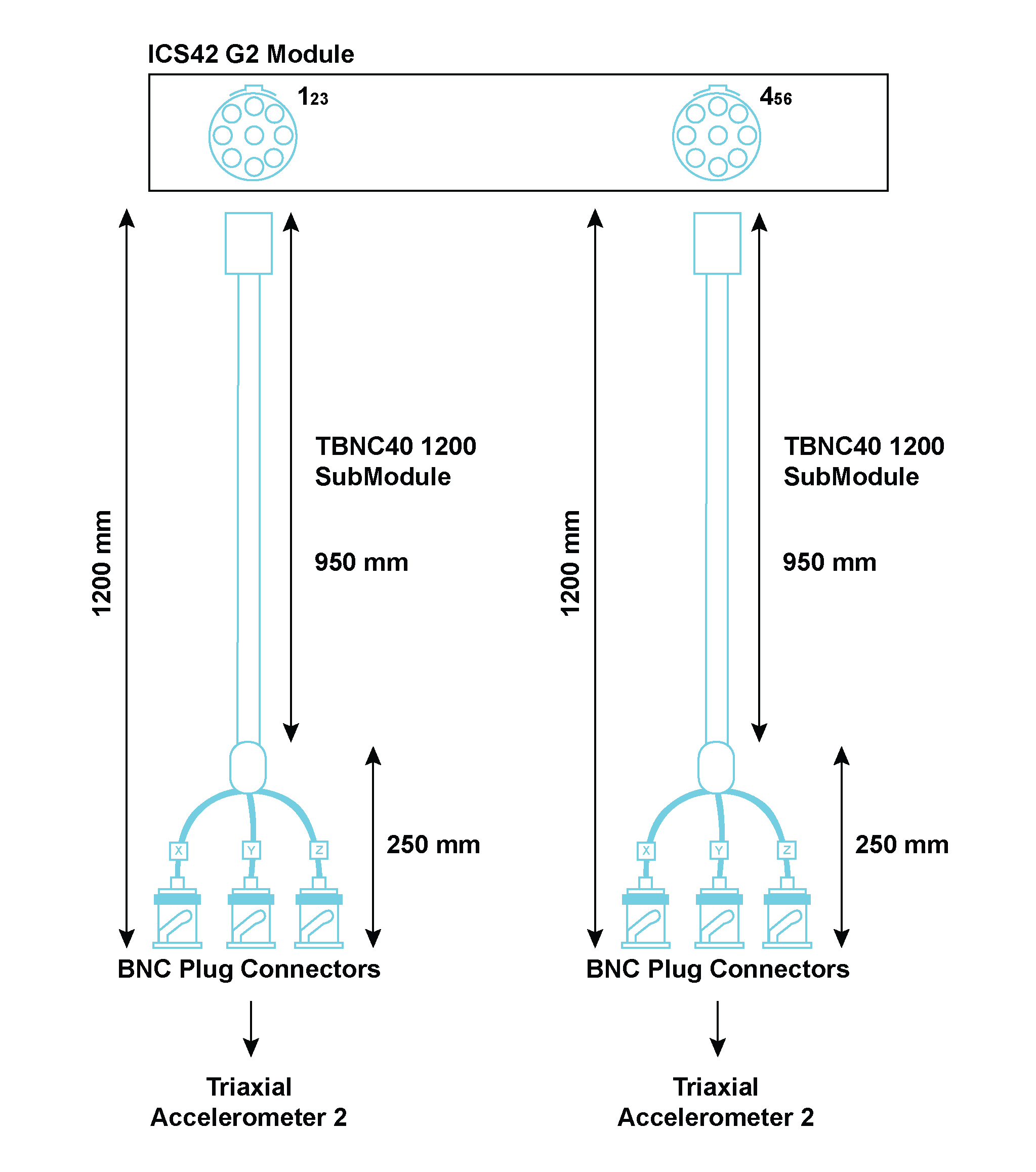
Connector Information and Pin Definitions
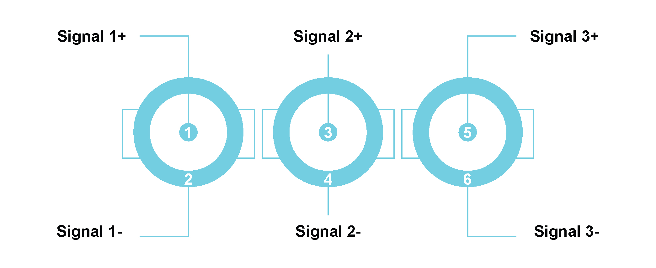
| Pin Number of TBNC40 | Signal Name | Channel on ICS42 | Triaxial Accelerometer pin | |
| Left Lemo® | Right Lemo® | |||
| 1 | Signal 1+ | Channel 1+ | Channel 4+ | X+ |
| 2 | Signal 1- | Channel 1- | Channel 4- | GNDx |
| 3 | Signal 2+ | Channel 2+ | Channel 5+ | Y+ |
| 4 | Signal 2- | Channel 2- | Channel 5- | GNDy |
| 5 | Signal 3+ | Channel 3+ | Channel 6+ | Z+ |
| 6 | Signal 3- | Channel 3- | Channel 6- | GNDz |
Pin descriptions of TBNC40, ICS42 and triaxial accelerometer
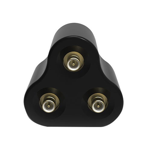
The TSMB10 is used to connect to the ICS42 Module. The Tri-SMB10 SubModule splits signals, from a 9-way LEMO® connector on the Module’s front panel, to 3 SMB connectors to easily connect sensors. Three SMB connectors are provided on the SubModule to interface to the appropriate triaxial or single axis accelerometer. The SubModule connects to the ICS42 Module through a 500 mm or 1200 mm fly-lead.
| TSMB10 options: | |
|---|---|
| TSMB10 500 | The SMB connectors connect to the ICS42 Module with a total cable length of 500 mm |
| TSMB10 1200 | The SMB connectors connect to the ICS42 Module with a total cable length of 1200 mm |
Where used:
With any ICP® based sensor commonly used to measure vibration, acceleration, force or pressure
With any voltage source up to ±10 V in voltage input mode
Connection diagram per channel
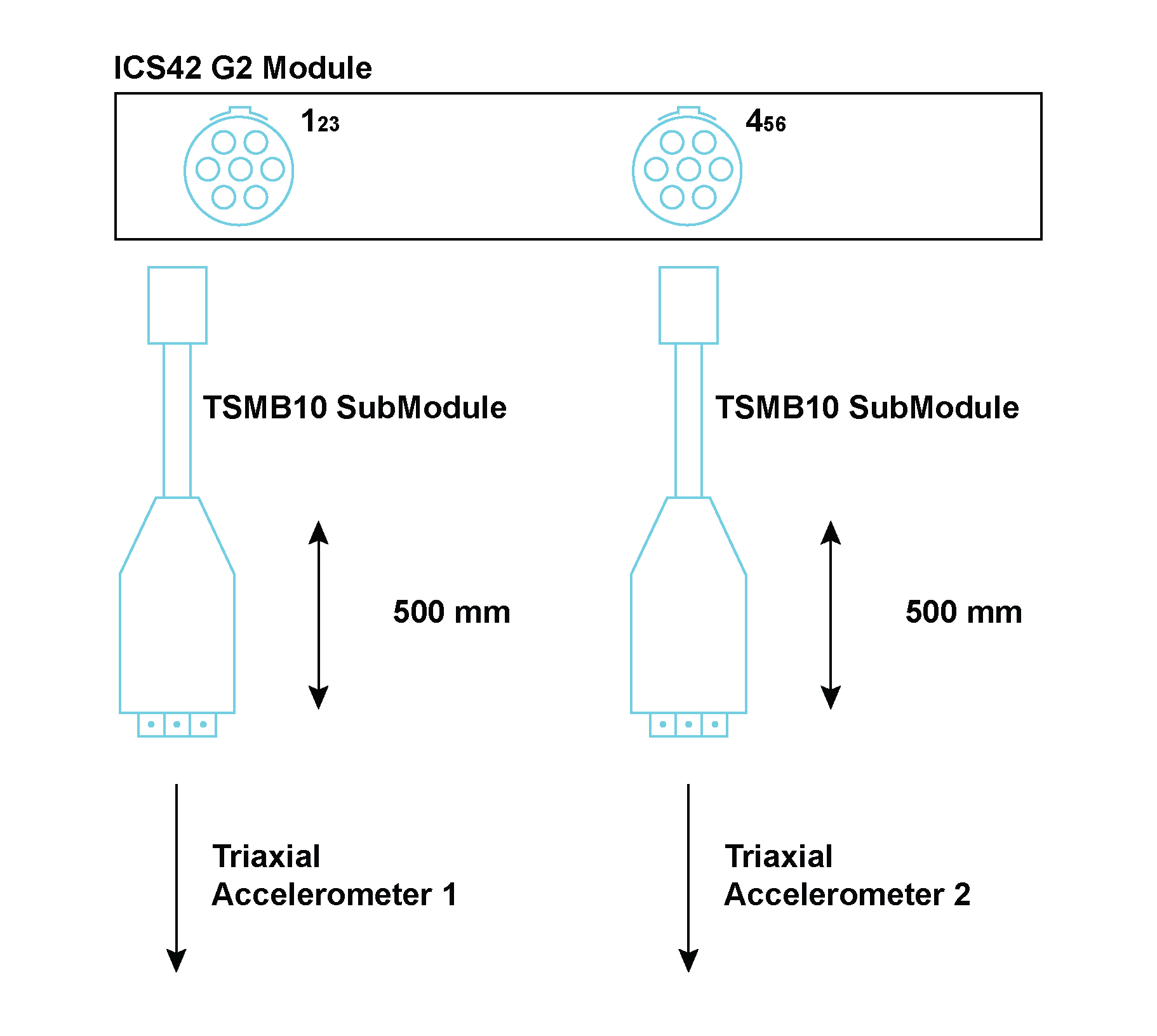
Connector Information and Pin Definitions
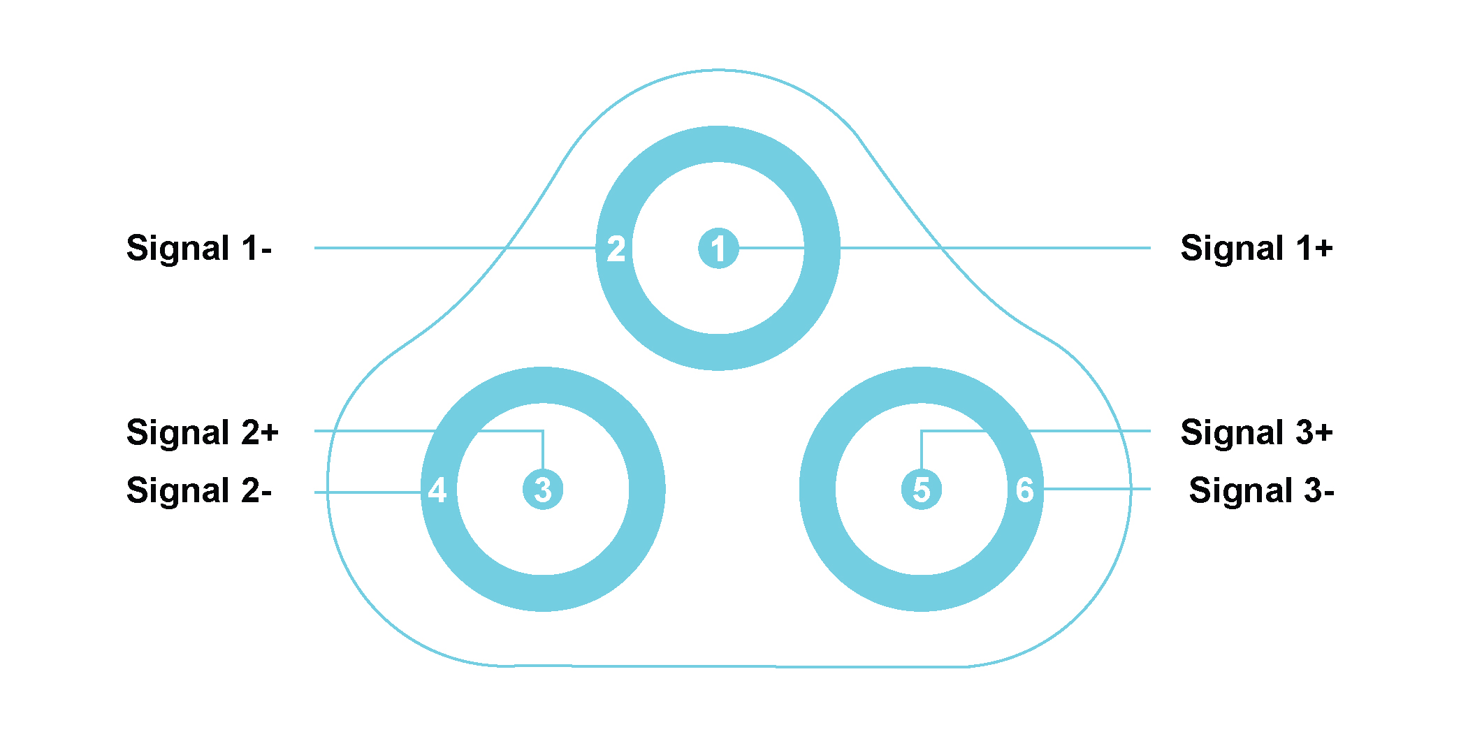
| Pin Number of TSMB10 | Signal Name | Channel on ICS42 | Triaxial Accelerometer pin | |
| Left Lemo® | Right Lemo® | |||
| 1 | Signal 1+ | Channel 1+ | Channel 4+ | X+ |
| 2 | Signal 1- | Channel 1- | Channel 4- | GNDx |
| 3 | Signal 2+ | Channel 2+ | Channel 5+ | Y+ |
| 4 | Signal 2- | Channel 2- | Channel 5- | GNDy |
| 5 | Signal 3+ | Channel 3+ | Channel 6+ | Z+ |
| 6 | Signal 3- | Channel 3- | Channel 6- | GNDz |
Pin descriptions of TSMB10, ICS42 and triaxial accelerometer
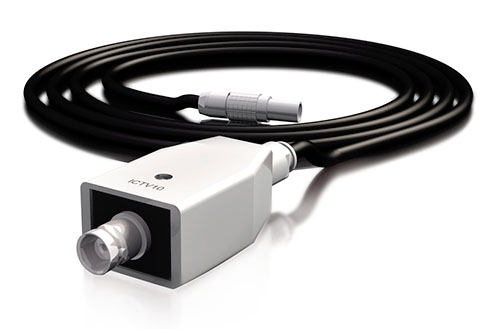
The ICTV11 is used to protect the ICT42 or ICT42S Module’s Tacho inputs from excessively high voltages. These may occur when inductive devices are discharged or when measuring close to high voltage circuitry. The SubModule contains high energy over-voltage dissipation devices. These devices limit the output voltage to reasonable values which will not destroy the internal circuitry of the ICT42 and ICT42S Modules. A BNC connector is provided on the SubModule to interface to the appropriate Tacho sensor. The SubModule connects to the ICT42 and ICT42S Module through a 300 mm fly-lead ending with a 4-pin LEMO® FGG.0B connector.
Where used:
Connection diagram per channel
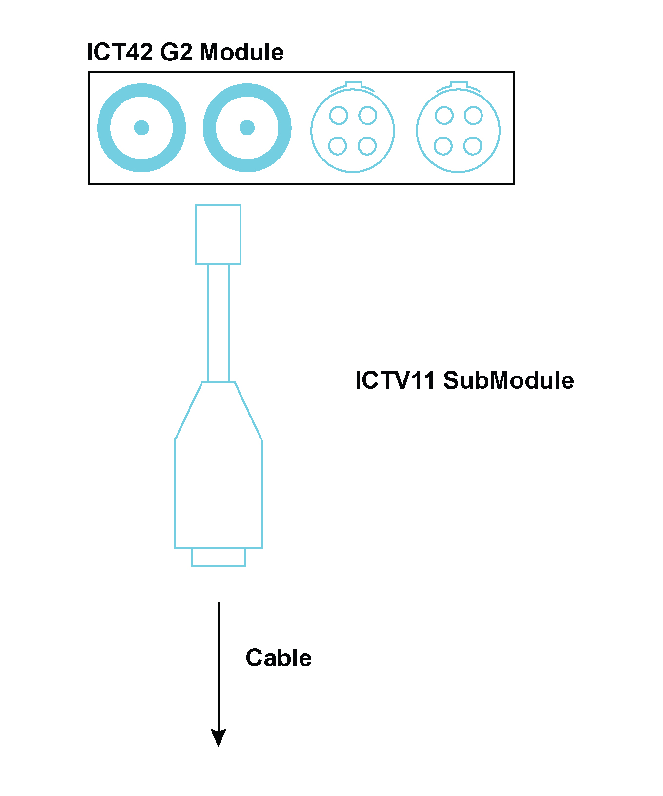
Connector Information and Pin Definitions

Pin 1: Signal +
Pin 2: Signal -

The FLXB20 SubModule provides an interface to a 9-pin D-sub connection. The FLXB20 SubModule is used to connect a FLX42 Module to a FlexRay™ network. It provides the interface between the 7-pin LEMO® connector on the FLX42 Module and the 9-pin D-sub connector on the FlexRay™ network.
Where used (FlexRay™):
One FLXB20 SubModule can connect a FLX42 Module to a FlexRay™ network (3000 mm cable length)
Designed as a SubModule used to connect one channel of a FLX42 Module to a FlexRay™ network
Accepts a single 7-pin LEMO® FGG 0B connector
The FLXB20 provides the interface to the 9-pin D-sub connector on the FlexRay™ network over a 3000 mm cable
The FLXB20 SubModule can also be used to connect a CAN42 Module to a CANbus network. Here it provides the interface between the 7-pin LEMO® connector on the CAN42 Module and the 9-pin D-sub connector on the CANbus network. Where Used (CANbus):
Connection diagram per channel
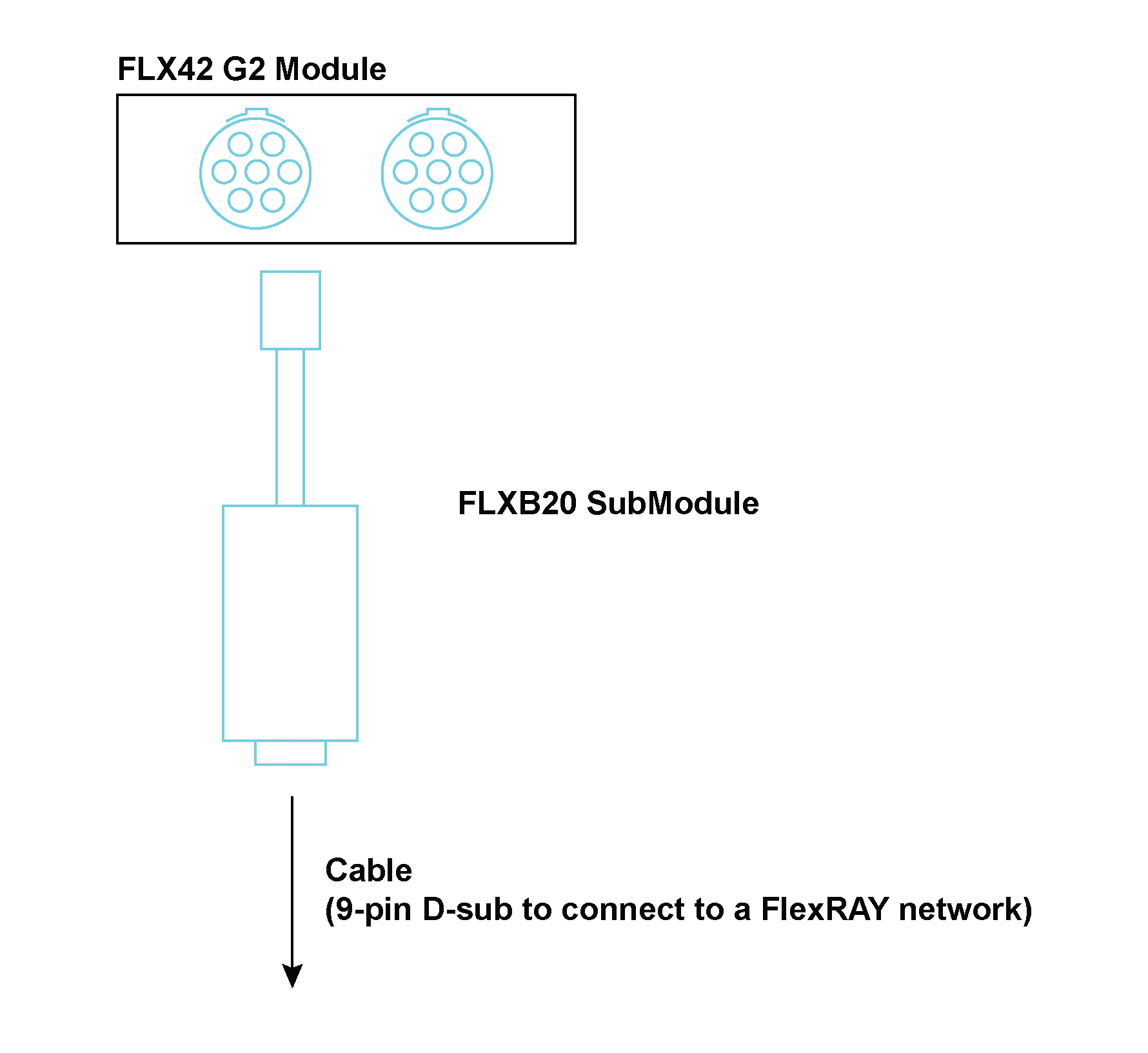
Connector Information and Pin Definitions

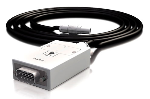
The CANC10 SubModule provides an interface to a 9-pin D-sub connection. The CANC10 SubModule is used to connect a CAN42S Module to a CANbus network. It provides the interface between the 7-pin LEMO® connector on the CAN42S Module and the 9-pin D-sub connector on the CANbus network.
Where used (CANbus):
Connection diagram per channel
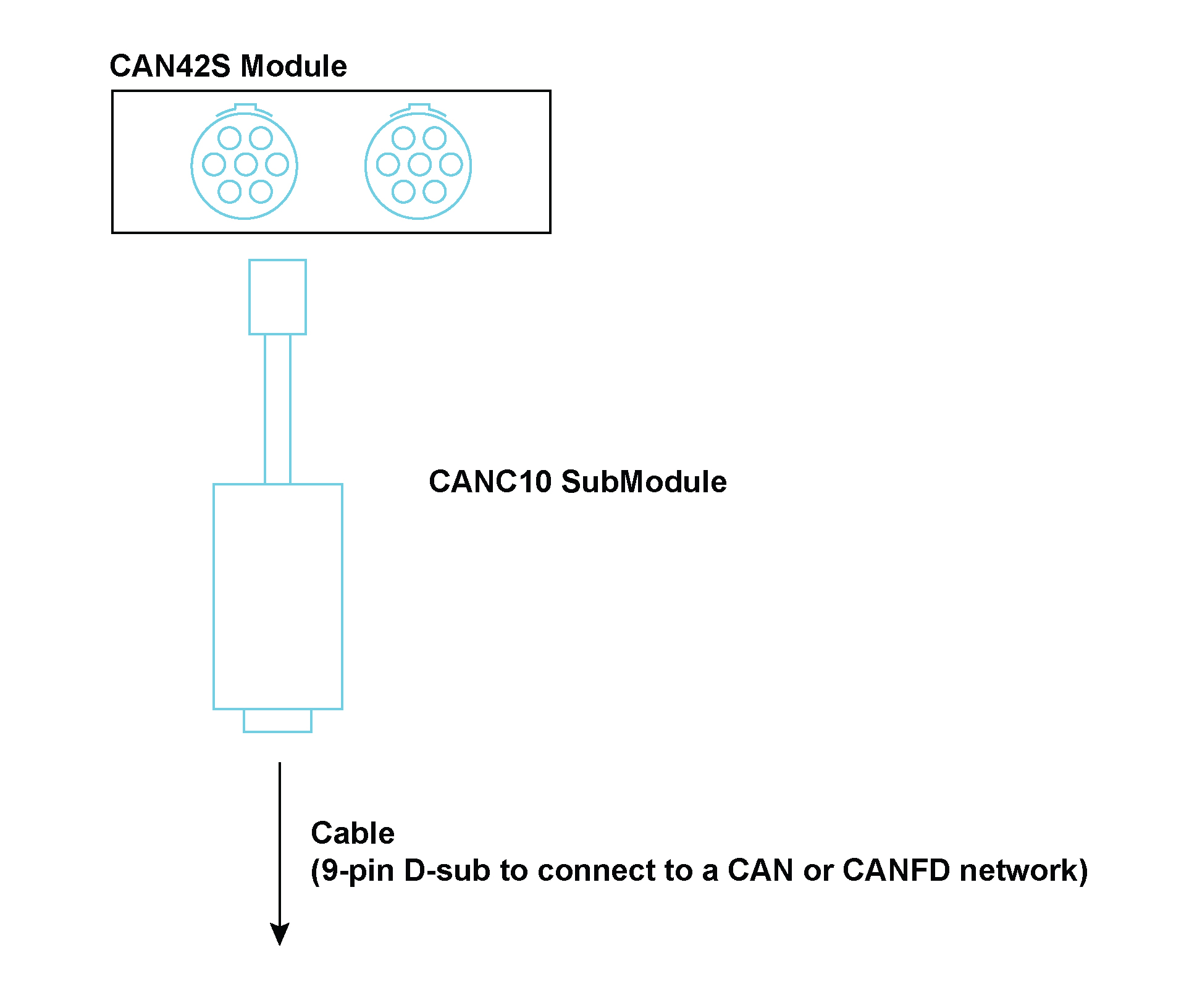
Connector Information and Pin Definitions
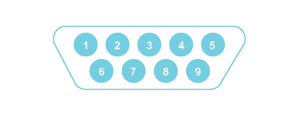
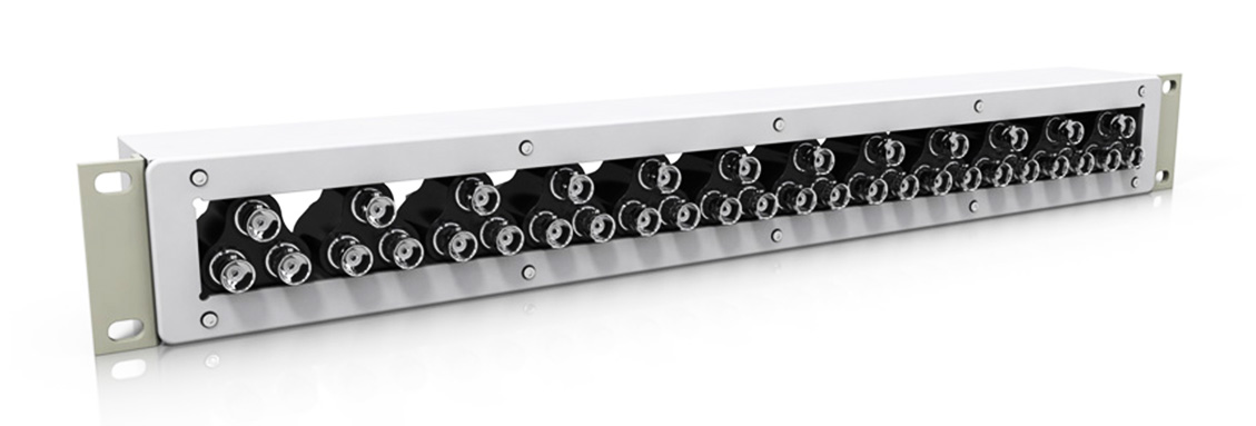
The SMRM10 is a panel designed to house SubModules. It can be used to house any of the various SubModules as all SubModules have the same height. The SMRM10 has been designed to be mounted in a 19-inch rack.
Where used:
Connection diagram per channel
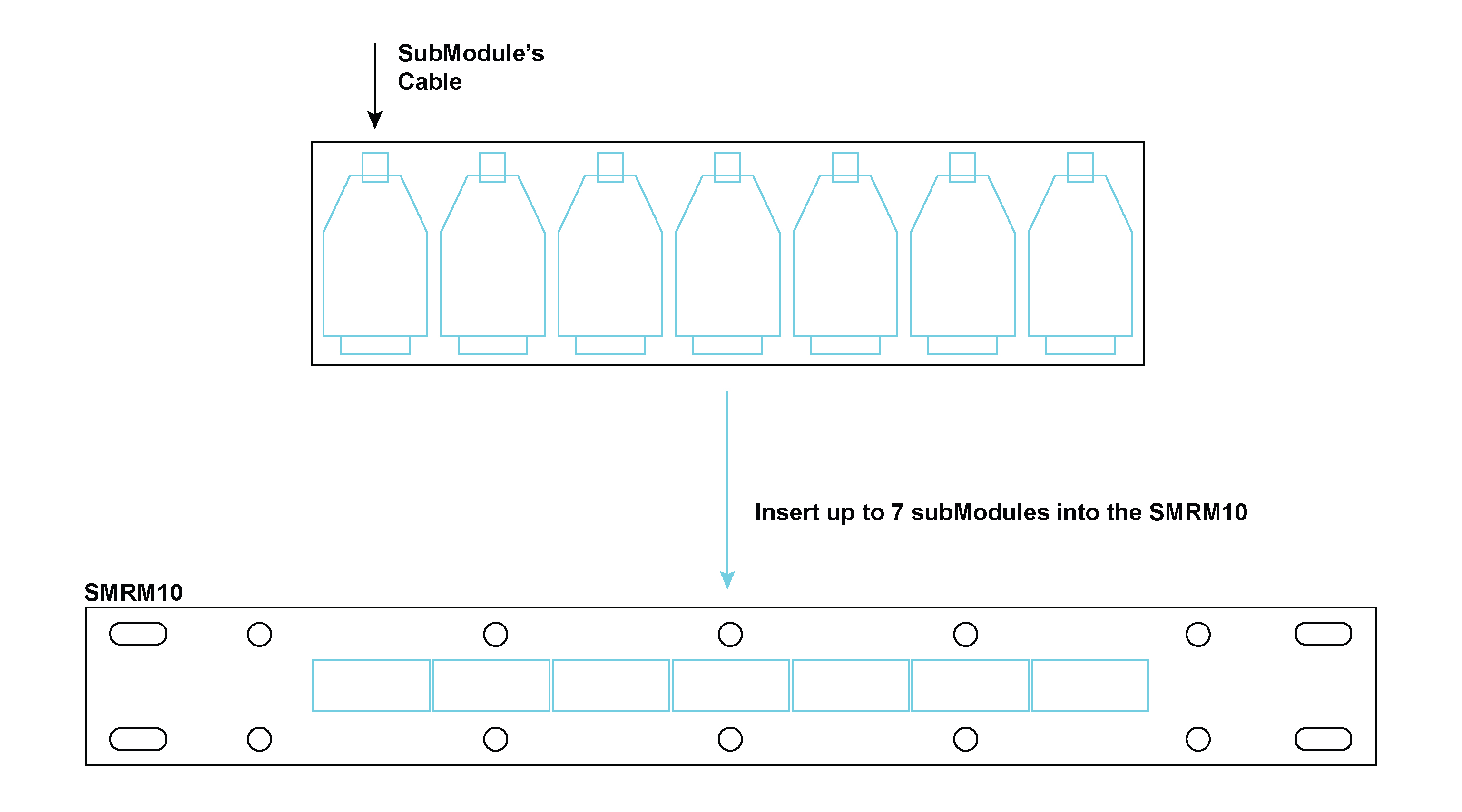
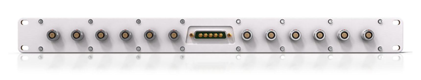
The PSDP10 is a multiport power distribution panel for powering multiple DECAQ Chassis. The panel (which is designed to be mounted in a 19-inch rack) is supplied power through a 5-pin high power D-subminiature port and provides power to 12 recipient DECAQ Chassis through 4-pin LEMO® connectors.
Where used:
Supplies the power for up to 12 DECAQ Chassis
Designed according to a 1.5 U form factor for rack-mounting in 19” racks
Accepts power through a 5-pin high power D-subminiature port
Provides twelve 4-pin LEMO® connectors
Connection diagram per channel
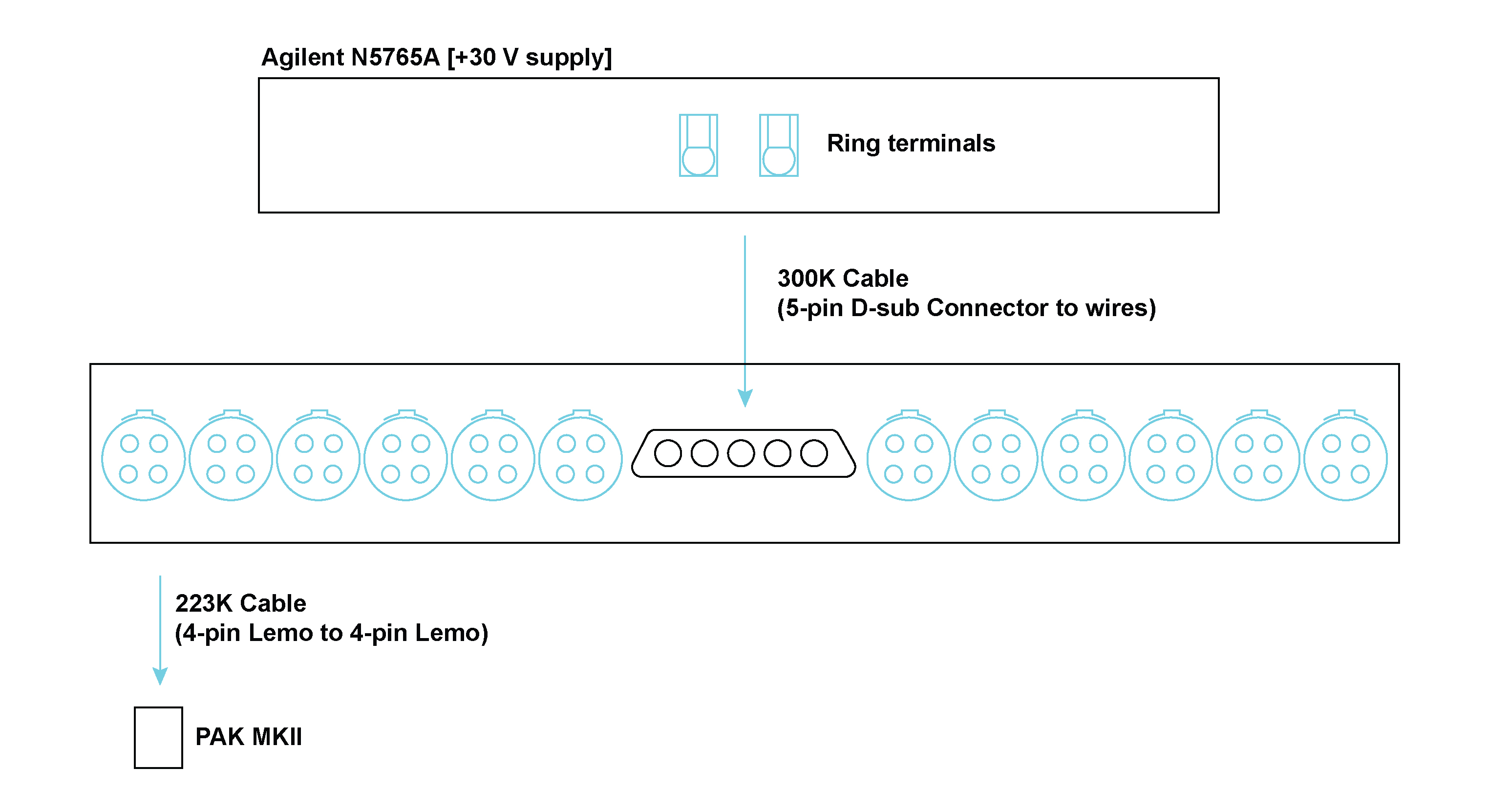
Connector Information and Pin Definitions
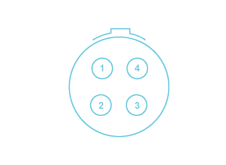

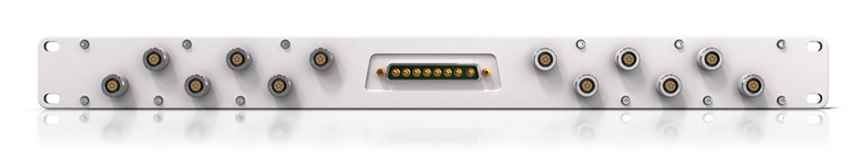
Similarly, the PSDP20 is a multiport power distribution panel for powering multiple ALOP10s. The panel is supplied power through an 8-pin high power D-subminiature port and provides power to the recipient boards through 5-pin LEMO® connectors.
Where used:
Connection diagram per channel
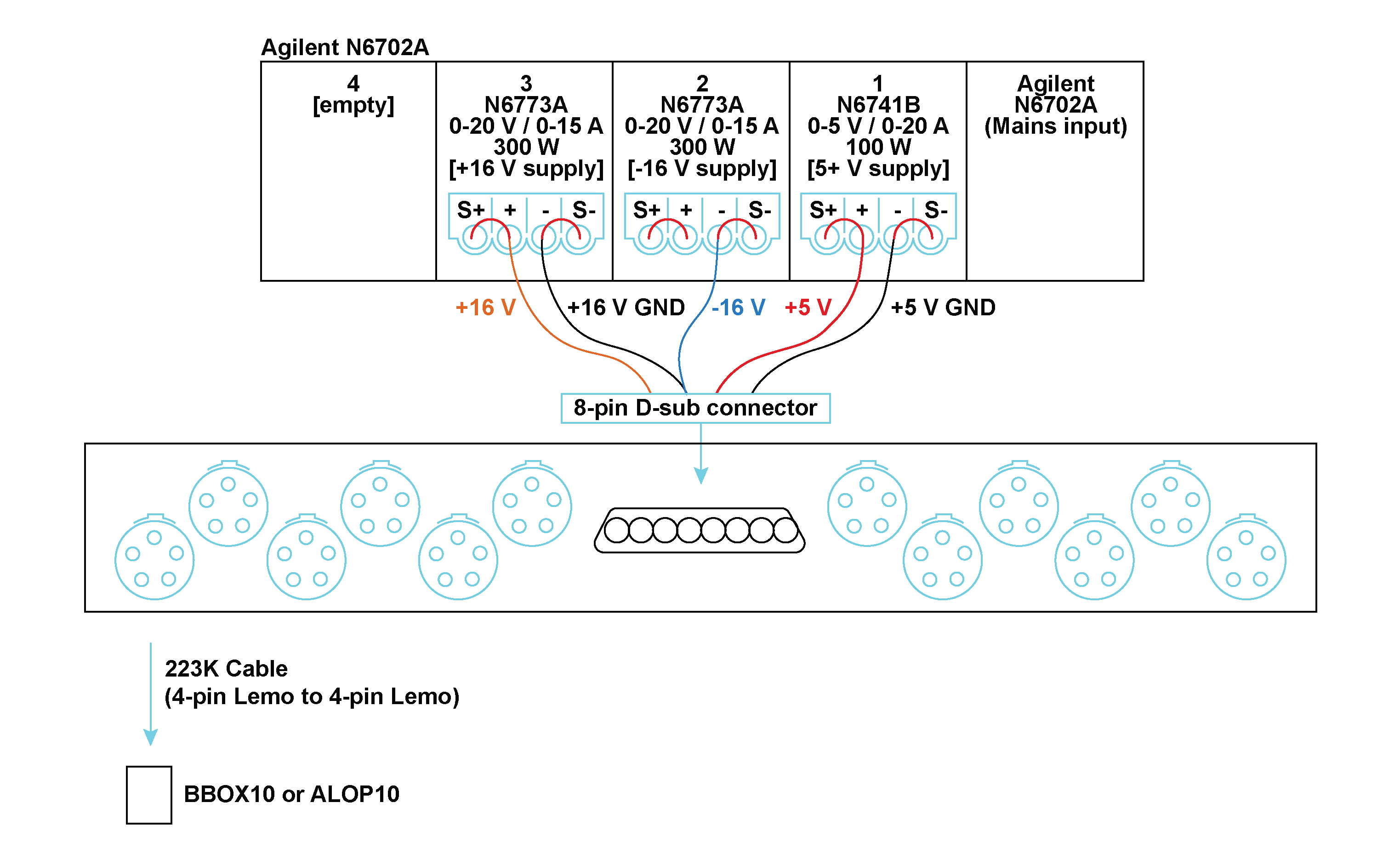
Connector Information and Pin Definitions
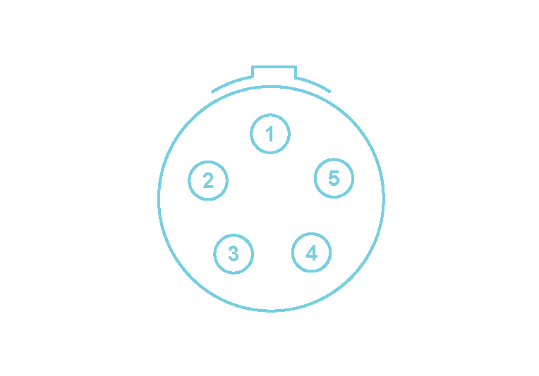

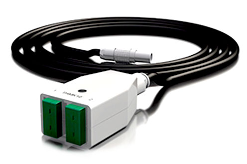
Seven thermocouple-based SubModules exist, each containing dedicated thermocouple connectors. Each SubModule contains a pair of miniature thermocouple connectors, of the appropriate alloy and color, according to either IEC or ANSI standards. Cold-junction-compensation is facilitated through the use of a 0.5 °C accurate temperature sensor in thermal contact with the connectors’ contacts. The SubModule type is identified through a TEDS interface.
Each SubModule connects to the THM42 Module through a 300 mm fly-lead ending with a 7-way LEMO® FGG 0B connector.
Connection diagram per channel
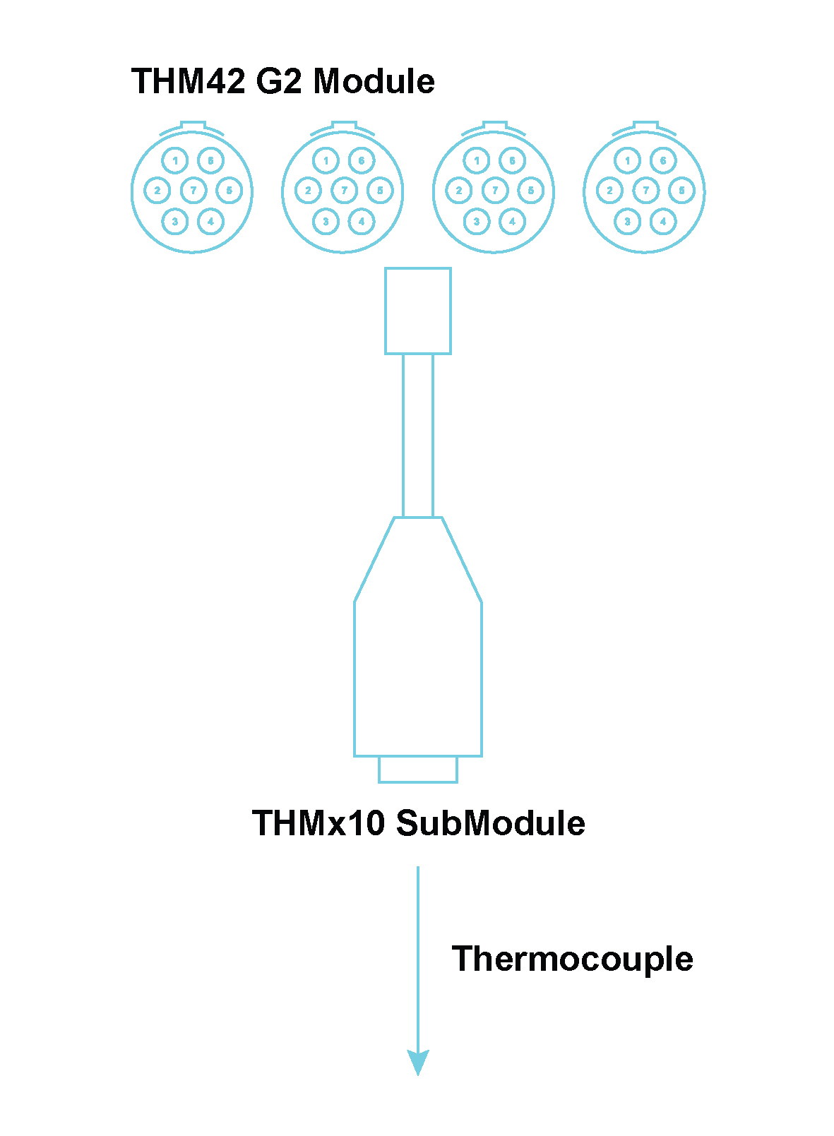
Connector Information and Pin Definitions
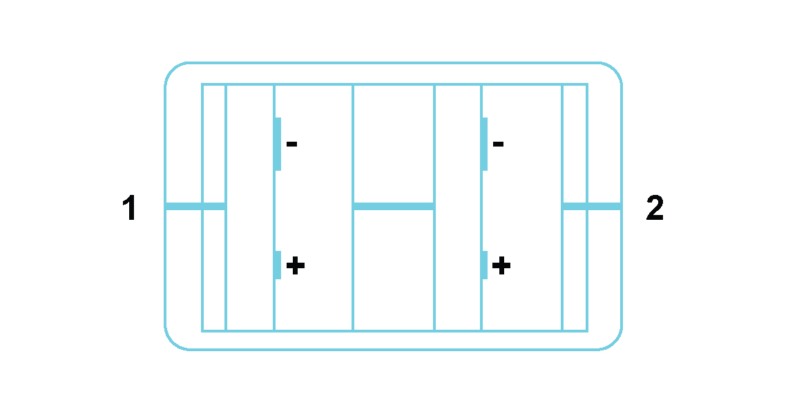
Miniature thermocouple connector 1 (and similarly thermocouple connector 2):
Pin +: Thermocouple +
Pin -: Thermocouple –
| These 7 SubModules can be listed as follows: | |
|---|---|
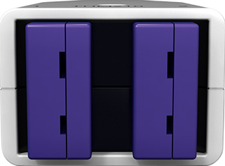 |
The THME10 SubModule contains Chromel/Constantan (NiCr/CuNi) alloys and has lilac connectors (IEC 584-3 and ANSI MC 96.1) |
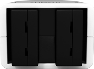 |
The THMJ10 SubModule contains Iron/ Constantan (Fe/CuNi) alloys and has black connectors (both IEC 584-3 and ANSI MC 96.1) |
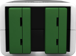 |
The THMK10 SubModule contains Chromel/Alumel (NiCr/NiAl) alloys and has green connectors (IEC 584-3) |
 |
The THMK10 SubModule contains Chromel/Alumel (NiCr/NiAl) alloys and has yellow connectors (ANSI MC 96.1) |
 |
The THMT10 SubModule contains Copper/Constantan (Cu/CuNi) alloys and has blue connectors (ANSI MC 96.1) |
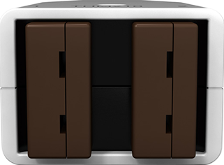 |
The THMT10 SubModule contains Copper/Constantan (Cu/CuNi) alloys and has brown connectors (IEC 584-3) |
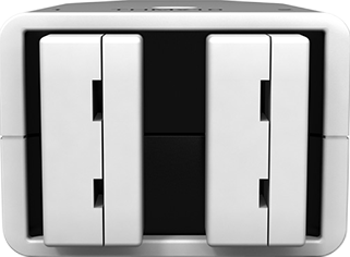 |
The THMU10 SubModule contains Copper/Copper (Cu/Cu) alloys and has white connectors |
Seven thermocouple-based SubModules

The THMP10 SubModule is used in conjunction with a THM42 Module to provide 2 sets of 4-way LEMO® EGG 0B connectors for use with 2 Pt100 sensors. These connectors provide current to a Pt100 sensor and sense the voltage across it. The SubModule type is identified through a TEDS interface. The THMP10 SubModule connects to the THM42 Module through a 300 mm fly-lead ending with a 7-way LEMO® FGG 0B connector.
Where used:
Connection diagram per channel
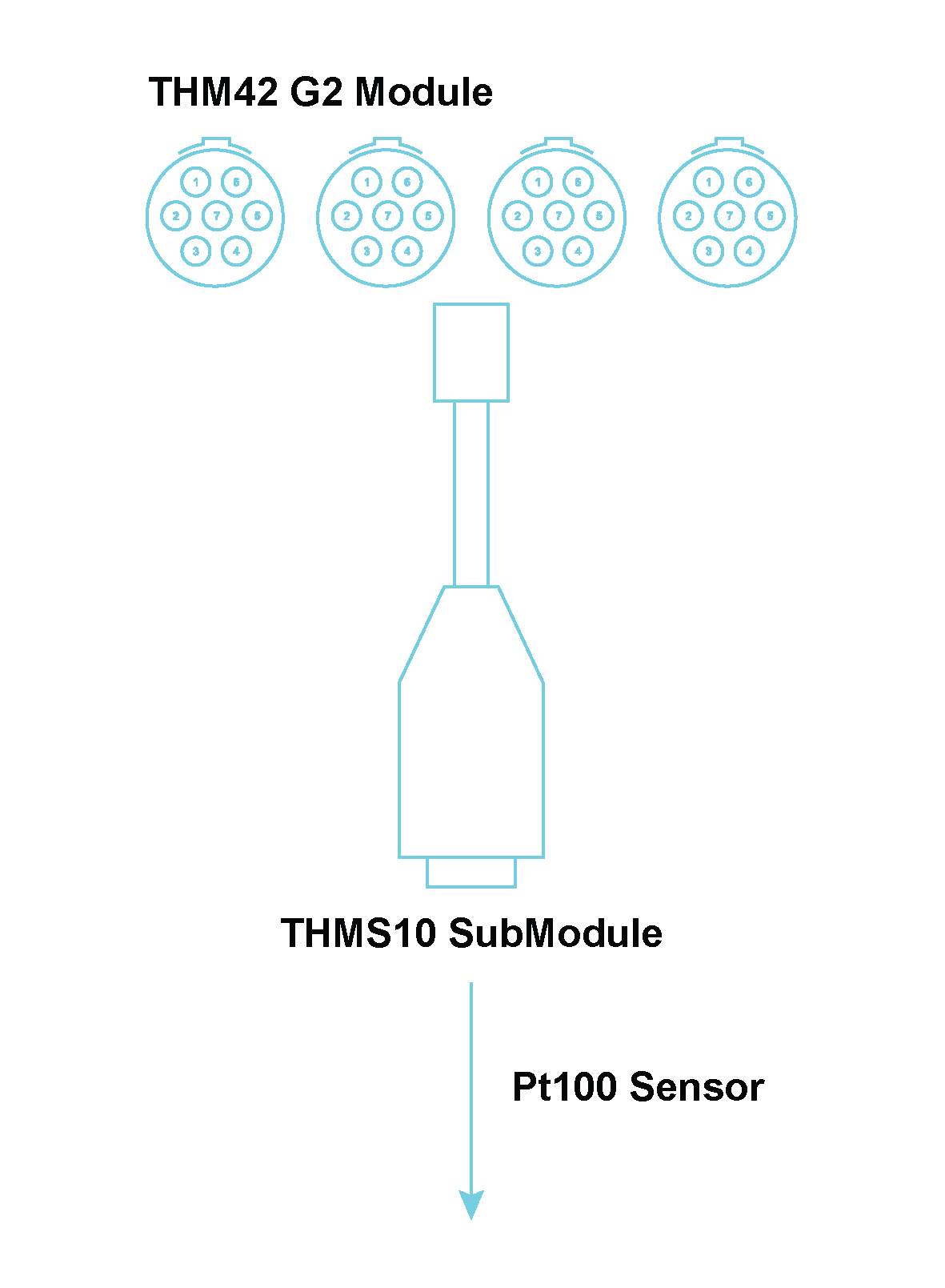
Connector Information and Pin Definitions
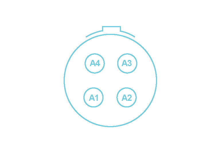
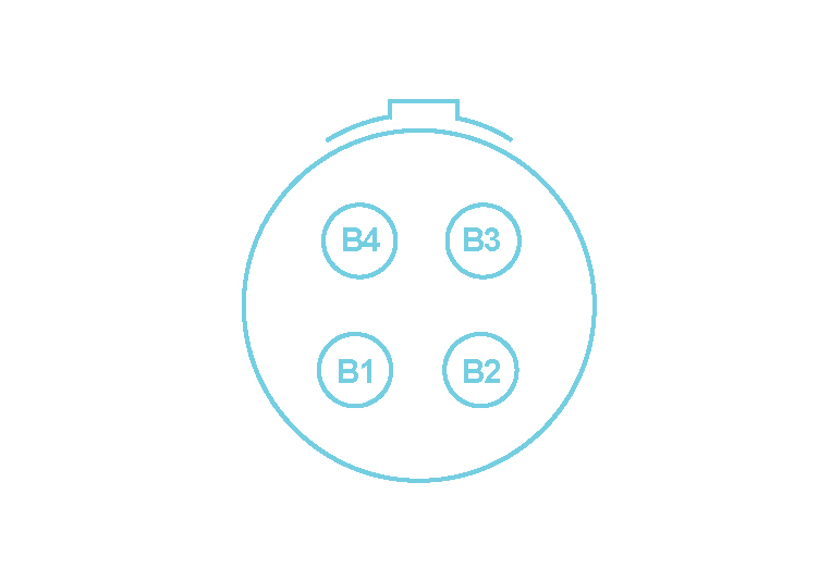
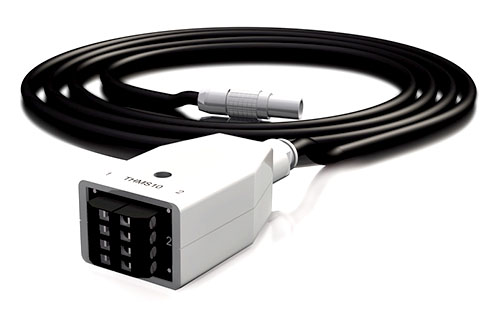
The THMS10 SubModule is used in conjunction with a THM42 Module to provide 2 sets of 4‑way general purpose screw terminals to connect to a pair of E, J, K or T thermocouples or a pair of Pt100 sensors. Cold-junction-compensation is facilitated through the use of a 0.5 °C accurate temperature sensor in thermal contact with the connectors’ contacts. Constant current is provided for Pt100 use. The SubModule type is identified through a TEDS interface. The THMS10 SubModule connects to the or THM42 Module through a 300 mm fly-lead ending with a 7-way LEMO® FGG 0B connector.
Where used:
Connection diagram per channel
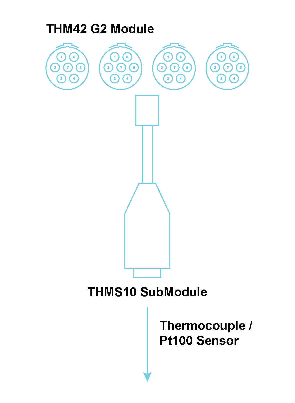
Connector Information and Pin Definitions

NOTE: The use of 2-wire and 3-wire Pt100 sensors is not recommended due to an increase in measurement errors brought about by the lead resistance.
The table below provides a summary of the connection procedures for thermocouples and Pt100 sensors when 2 sensors are being connected to the THMS10.
| Pin Number | Function | Sensor Type | |||
|---|---|---|---|---|---|
| Thermocouple | Pt100 (4-wire) | Pt100 (3-wire) | Pt100 (2-wire) | ||
| A1 | Excitation0+ | NC [1] | Positive current lead of first Pt100 | Positive current lead of first Pt100 | Jumper between pins A1 and A2 [2] |
| A2 | Signal0+ | Positive lead of first thermocouple | Positive signal lead of first Pt100 | Positive signal lead of first Pt100 | Positive signal lead of first Pt100 |
| A3 | Signal0- | Negative lead of first thermocouple | Negative signal lead of first Pt100 | Negative signal lead of first Pt100 | Negative signal lead of first Pt100 |
| A4 | Excitation0- | NC | Negative current lead of first Pt100 | Jumper between pins A3 and A4 | Jumper between pins A3 and A4 |
| B1 | Excitation1+ | NC | Positive current lead of second Pt100 | Positive current lead of second Pt100 | Jumper between pins B1 and B2 |
| B2 | Signal1+ | Positive lead of second thermocouple | Positive signal lead of second Pt100 | Positive signal lead of second Pt100 | Positive signal lead of second Pt100 |
| B3 | Signal1- | Negative lead of second thermocouple | Negative signal lead of second Pt100 | Negative signal lead of second Pt100 | Negative signal lead of second Pt100 |
| B4 | Excitation1- | NC | Negative current lead of second Pt100 | Jumper between pins B3 and B4 | Jumper between pins B3 and B4 |
Connections between 2 Thermocouple/Pt100 Sensors and a THMS10
[1] Not connected
[2] The jumper connection is not made by the THMS10 internally and must therefore be made by the user externally
The table below provides a summary of the connection procedures for thermocouples and Pt100 sensors, when 1 sensor is being connected to channel 1 of the THMS10.
| Pin Number | Function | Sensor Type | |||
|---|---|---|---|---|---|
| Thermocouple | Pt100 (4-wire) | Pt100 (3-wire) | Pt100 (2-wire) | ||
| A1 | Excitation0+ | NC[1] | Positive current lead of Pt100 | Positive current lead of Pt100 | Jumper between pins A1 and A2 [2] |
| A2 | Signal0+ | Positive lead of thermocouple | Positive signal lead of Pt100 | Positive signal lead of Pt100 | Positive signal lead of Pt100 |
| A3 | Signal0- | Negative lead of thermocouple | Negative signal lead of Pt100 | Negative signal lead of Pt100 | Negative signal lead of Pt100 |
| A4 | Excitation0- | NC | NC | NC | NC |
| B1 | Excitation1+ | NC | NC | NC | NC |
| B2 | Signal1+ | NC | NC | NC | NC |
| B3 | Signal1- | NC | NC | NC | NC |
| B4 | Excitation1- | NC | Negative current lead of Pt100 | Jumper between pins A3 and B4 | Jumper between pins A3 and B4 |
Connections between 1 Thermocouple/Pt100 Sensor and channel 1 of the THMS10
[1] Not connected
[2] The jumper connection is not made by the THMS10 internally and must therefore be made by the user externally
The table below provides a summary of the connection procedures for thermocouples and Pt100 sensors, when 1 sensor is being connected to channel 2 of the THMS10.
| Pin Number | Function | Sensor Type | |||
|---|---|---|---|---|---|
| Thermocouple | Pt100 (4-wire) | Pt100 (3-wire) | Pt100 (2-wire) | ||
| A1 | Excitation0+ | NC [1] | Positive current lead of Pt100 | Positive current lead of Pt100 | Jumper between pins A1 and B2 [1] |
| A2 | Signal0+ | NC | NC | NC | NC |
| A3 | Signal0- | NC | NC | NC | NC |
| A4 | Excitation0- | NC | NC | NC | NC |
| B1 | Excitation1+ | NC | NC | NC | NC |
| B2 | Signal1+ | Positive lead of thermocouple | Positive signal lead of Pt100 | Positive signal lead of Pt100 | Positive signal lead of Pt100 |
| B3 | Signal1- | Negative lead of thermocouple | Negative signal lead of Pt100 | Negative signal lead of Pt100 | Negative signal lead of Pt100 |
| B4 | Excitation1- | NC | Negative current lead of Pt100 | Jumper between pins B3 and B4 | Jumper between pins B3 and B4 |
Connections between 1 Thermocouple/Pt100 Sensor and channel 2 of the THMS10
[1] Not connected
[2] The jumper connection is not made by the THMS10 internally and must therefore be made by the user externally
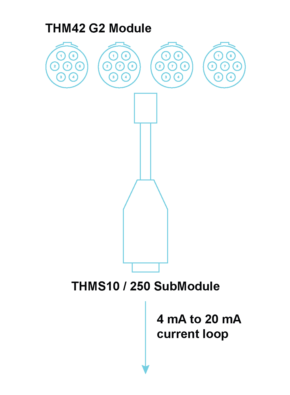
The THMS10/250 SubModule is used in conjunction with a THM42 Module to provide 2 sets of 4‑way general purpose screw terminals to connect to two constant current signals from sensors between 4 mA and 20 mA. Two precision 250 Ω resistors convert the constant current signals to voltage signals between 1 V and 5 V. The SubModule is identified through a TEDS interface. The THMS10/250 SubModule connects to the THM42 through a 300 mm fly-lead ending with a 7-way LEMO® FGG 0B connector.
Where used:
Connection diagram per channel
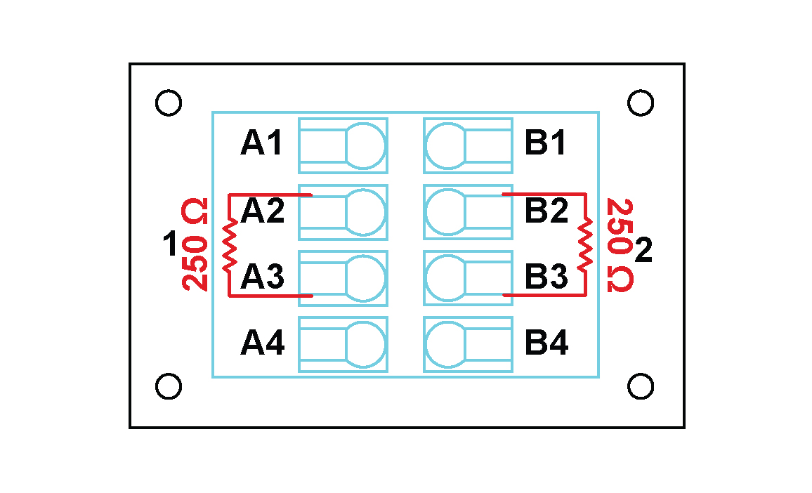
Connector Information and Pin Definitions
NOTE: The 250 Ω resistor is internal in the THMS10/250 and the user should not add the resistor to the pins.
The table below provides a summary of the connection procedures for sensors with a 4 mA to 20 mA current output that are being connected to the THMS10/250.
| Pin Number | Function | Sensor with 4 mA to 20 mA current output |
|---|---|---|
| A1 | Excitation0+ | NC [1] |
| A2 | Signal0+ | Positive lead of first sensor |
| A3 | Signal0- | Negative lead of first sensor |
| A4 | Excitation0- | NC |
| B1 | Excitation1+ | NC |
| B2 | Signal1+ | Positive lead of second sensor |
| B3 | Signal1- | Negative lead of second sensor |
| B4 | Excitation1- | NC |
Connections between two 4 mA to 20 mA output current sensors and a THMS10/250
[1] Not connected
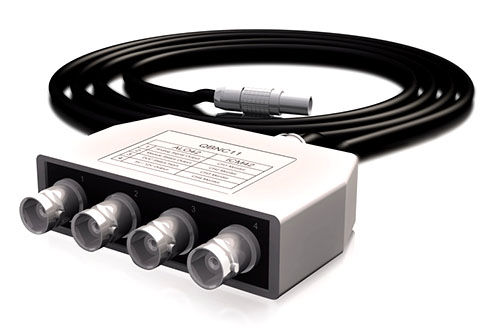
The Quad BNC (QBNC) is a SubModule that is used to split signals from a 7-pin LEMO® connector to 4 BNC connectors. A sticker on top indicates with which Modules the QBNC is compatible, and how the signals are mapped.
Where used:
Splits the signals coming from an ALO42S Module
Designed as a SubModule used to expand the capacity of an ALOP42S Module
Accepts one 7-pin LEMO® FGG 0B connector
Provides 4 BNC connectors to split the signals as follows:
Connection diagram per channel
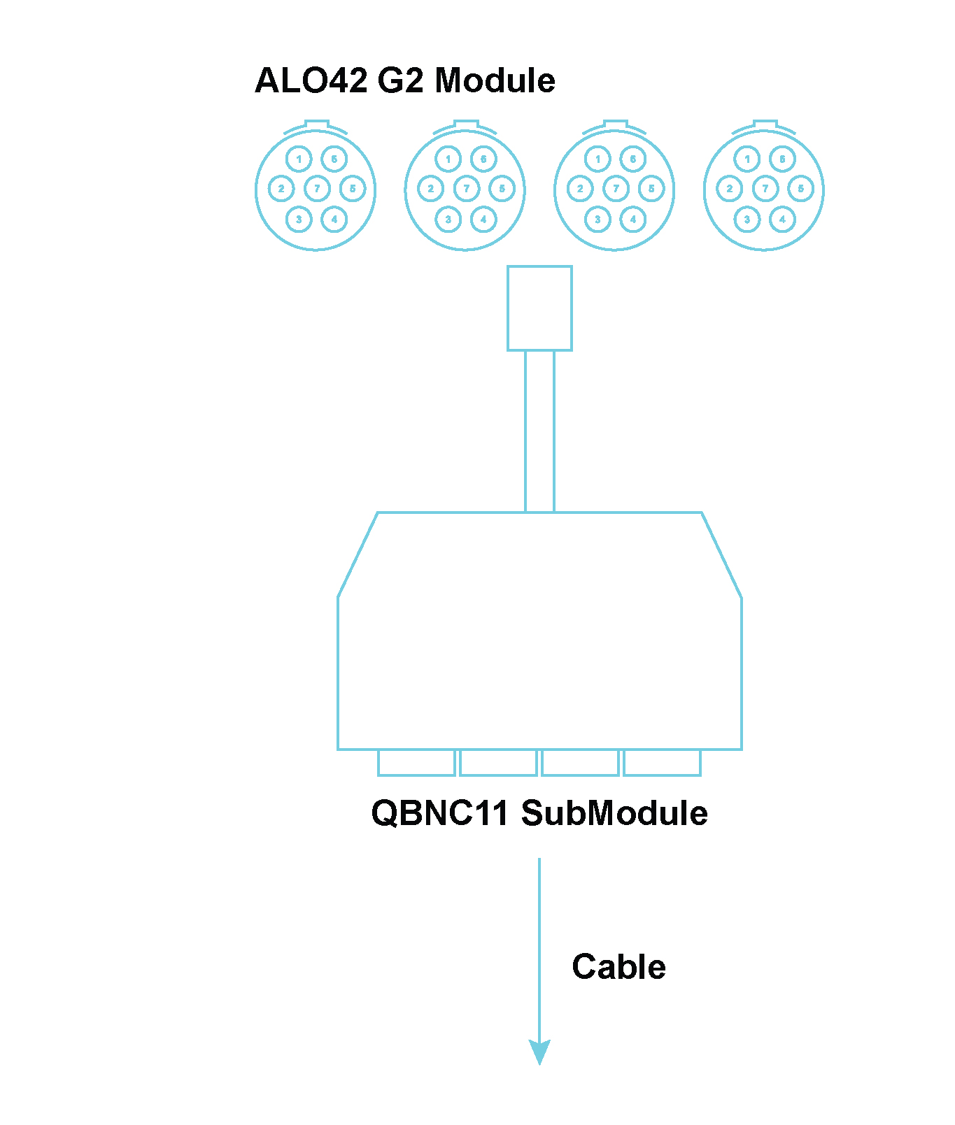
Connector Information and Pin Definitions

Pin 1: 5 V / 12 V Output +
Pin 2: 5 V / 12 V Output -
QBNC11 Pinouts when connected to an ALO42S Module
The 214K is a standard length power cable for powering combined power supply and controller boards from a car cigarette lighter.
| Length | Connector 1 | Connector 2 | Current Rating |
|---|---|---|---|
| 2 m | 4-way LEMO® (FGG.1B.304) with black bend relief. | Cigarette lighter plug. | 15 A |
The 230K is a standard length power cable for powering combined power supply and controller boards from a Mean Well power supply.
| Length | Connector 1 | Connector 2 | Current Rating |
|---|---|---|---|
| 1 m | 4-way LEMO® (FGG.1B.304) with red bend relief. | 4-way female DC power supply. | 15 A |
The 231K is a variable length power cable for powering combined power supply and controller boards from a Mean Well power supply.
| Length | Connector 1 | Connector 2 | Current Rating |
|---|---|---|---|
| Variable | 4-way LEMO® (FGG.1B.304) with red bend relief. | 4-way female DC power supply. | 15 A |
The 216K is a standard length power cable for powering combined power supply and controller boards from a desktop power supply (e.g. a TDK Lambda UP36-12).
| Length | Connector 1 | Connector 2 | Current Rating |
|---|---|---|---|
| 2 m | 4-way LEMO® (FGG.1B.304) with black bend relief. | 2 stackable banana plugs,1 red and 1 black. | 20 A |
The 221K is a variable length power cable for powering combined power supply and controller boards from a desktop power supply (e.g. a TDK Lambda UP36-12).
| Length | Connector 1 | Connector 2 | Current Rating |
|---|---|---|---|
| Variable | 4-way LEMO® (FGG.1B.304) with black bend relief. | 2 stackable banana plugs,1 red and 1 black. | 20 A |
The 223K is a standard length power cable for powering combined power supply and controller boards from a PSDP10.
| Length | Connector 1 | Connector 2 | Current Rating |
|---|---|---|---|
| 3 m | 4-way LEMO® (FGG.1B.304) with black bend relief. | 4-way LEMO® (FGG.1B.304) with black bend relief. | 20 A |
The 001K is a standard length sensor cable used to connect deflection bridge sensors to WSB42 and WSB42X Modules.
| Length | Connector 1 | Connector 2 |
|---|---|---|
| 2 m | 7-way LEMO® (FGG.0B.307) with blue bend relief | 7 unconnected wires (brown, red, orange, yellow, green, blue, black) |
The 008K is a variable length sensor cable used to connect deflection bridge sensors to WSB42 and WSB42X Modules.
| Length | Connector 1 | Connector 2 |
|---|---|---|
| Variable | 7-way LEMO® (FGG.0B.307) with blue bend relief | 7 unconnected wires (brown, red, orange, yellow, green, blue, black) |
The 010K is a standard length signal cable that disconnects the shield of an MIC42X Module.
| Length | Connector 1 | Connector 2 |
|---|---|---|
| 300 mm | 7-way LEMO® (FGG.1B.307) with black bend relief | 7-way LEMO® (PHG.1B.307) with black bend relief |
The 013K is a standard length signal cable that connects a CHG42S Module to a BNC socket.
| Length | Connector 1 | Connector 2 |
|---|---|---|
| 1 m | 10 - 32 Microdot | BNC plug |
The 023K is a standard length signal cable that connects an ALO42S Module to an ALOP10 SubModule.
| Length | Connector 1 | Connector 2 |
|---|---|---|
| 3 m | 4 7-way LEMO® (FGG.0B.307) | Male 37-way D-sub |
The 025K is a standard length signal cable that converts the SMB output of a Module to a BNC output.
| Length | Connector 1 | Connector 2 |
|---|---|---|
| 1 m | SMB socket | BNC plug |
All rights are reserved. No part of this publication may be reproduced, shared with a third party, stored in a retrieval system or transmitted in any form (mechanical, electronic, photocopying, recording or other) without the prior written permission of Mecalc. All information in this document, including drawings, technical descriptions and images, remains the property of Mecalc.
Every precaution has been taken to provide the most relevant and accurate information regarding the products discussed in this manual. However, as Mecalc is constantly improving and updating its products, this information is subject to change without notice.
Extended warranty options are available, please contact your supplier for more information.
Mecalc shall not be responsible for conformity with any standards, codes or regulations that may apply to the combination of products in the customer’s application or use of the products.
At the customer’s request Mecalc can provide applicable certification documents identifying ratings and limitations of use that apply to products. However, this information by itself is not sufficient for a complete determination of the suitability of the products in combination with the end product, machine, system or other application or use.
The following are examples of typical applications. However, this is neither an exhaustive list nor intended to imply that products will always be suitable for use in these instances:
Please know and observe all prohibitions of use applicable to the products.
| Please note |
|---|
| Never use the products for an application involving serious risk to life or property without ensuring that the system as a whole has been designed to address the risks, and that the Mecalc products are properly rated and installed for the intended use within the overall equipment or system. |
Mecalc cannot be responsible for any consequences as a result of the user’s programming of a programmable product.
Performance data given in this manual are provided as a guide for the user in determining suitability and do not constitute a warranty. The data may represent the results of Mecalc ’s test conditions and users will have to correlate those results with actual application requirements. Actual performance is subject to the MECALC Warranty and Limitations of Liability.
The information in this manual has been carefully checked and is believed to be accurate. However, no responsibility is assumed for clerical, typographical or proofreading errors or omissions.
UM250401
![]()
MECALC.com
© 2025 Mecalc (Pty) Ltd. QuantusSeries and the Q icon are registered trademarks of Mecalc (Pty) Ltd. Information is provided “as is” without warranties or guarantees regarding accuracy, completeness, or suitability for any purpose. Mecalc assumes no liability for its use. In keeping with our commitment to continuous product improvement, information contained herein is subject to change.